T775R SERIES 2000 ELECTRONIC STAND-ALONE CONTROLLER
62-0249—13 12
IMPORTANT
1. This action sets the maximum setpoint value of
all outputs to the setpoint high limit maximum.
2. Setting the high limit setpoint maximum is
irreversible. If you perform the action
inadvertently and this setpoint adversely affects
the control of your system, you must replace the
controller.
Programming the T775R
Controller
To program the controller, select one of the following
procedures depending on whether the Reset function is to
be used:
• Program Outputs for Reset — See “1. Programming
Outputs (Relay and Mod) with Reset” on page 12
• Program Outputs for No Reset — Refer to
“2. Programming Outputs (Relay and Mod) with No
Reset” on page 16
When programming is complete, you may continue with
“4. Scheduling” on page 31 or, for advanced options,
continue with “3. Setup (Advanced Options)” on page 19.
1. PROGRAMMING OUTPUTS
(RELAY AND MOD) WITH
RESET
The T775R can be programmed for Reset or No Reset for
each output. From the factory, the T775R is programmed
for No Reset. This section describes the steps necessary
to program the controller for Reset.
To use the Reset feature, the first output (MOD 1 or Relay
1 depending on the model) must be set to Reset=YES in
Setup mode (See “1.1. Setting Up the Controller for
Reset”).
The reset curve established when programming the first
output (MOD 1) is then used for all subsequent outputs
that are configured for Reset, and each of those outputs
will be offset from this curve.
For all outputs that will follow a reset curve, be sure to
configure for Reset=YES in the setup mode. Choose
Reset YES or NO for all other outputs you wish to reset,
then press the HOME button to record your selection.
If using the time clock or DI to go to setback,
the T775R will shift the reset curve up or down
and cause the controlled setpoint to exceed
either the entered reset max. temp or min.
temp (dropping below reset minimum is most
common, since setback is normally below
setpoint). If this is not desired, either do not
use setback, or adjust the min. and max.
values entered so that critical setpoints are
not exceeded in the setback mode.
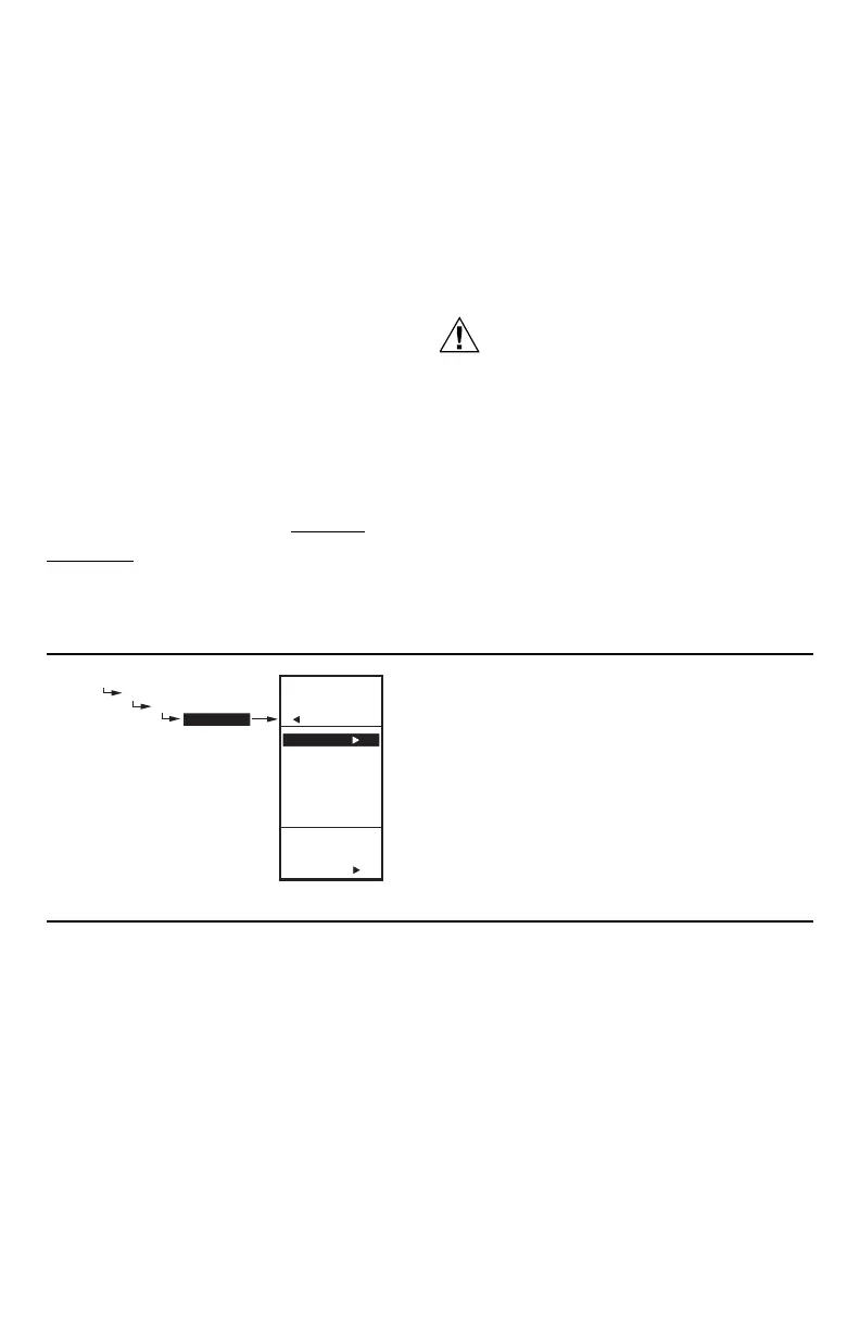
Fig. 24. Reset Setup.
1.1. Setting Up the Controller for Reset
1. Press and hold the MENU button for five seconds to
enter Setup mode.
2. Then choose:
OUTPUTS
RELAY 1 (or MOD1 if Mod outputs present)
RESET
then select YES -BOILER or YES-OTHER.
You can now press the HOME button to exit Setup mode
and continue with “Determining and Setting the Reset
Values”.
Determining and Setting the Reset
Values
NOTE: When using the Reset feature, Sensor A must
be sensing the controlled temperature (e.g.
Boiler), Sensor B must be sensing the reset-
ting temperature (e.g. outdoor temp).
To program an output for Reset, refer to the values as
shown in the examples below and in Fig. 25 on page 13.
Choose your own appropriate values for Sensor A
maximum and minimum and Sensor B maximum and
minimum.
Reset Example: (Refer to Fig. 25 on page 13)
• Sensor A is the boiler sensor and Sensor B is the
outdoor sensor.
• Maximum boiler temperature desired is 210°F (99°C)
when the outdoor temperature is 20°F (-7°C).
• Minimum boiler temperature desired is 160°F (71°C)
when the outdoor temperature is 70°F (21°C).
• With the above settings example, when the outdoor
temperature is 50°F (10°C), the effective setpoint is
180°F (82°C).
Setback (optional) Example: (Refer to Fig. 25
on page 13)
• Setback of -10°F (-12°C) is used to drop the
temperature at night by 10°F (-12°C).
• With the above settings example, when the outdoor
temperature is 50°F (10°C), the effective setback
setpoint is 170°F (77°C) (180°F (82°C) setpoint minus
the 10°F (-12°C) setback).
NOTES:
SETUP
OUTPUTS
RELAY 1 (or MOD1)
RESET
SETUP
OUTPUTS
RELAY 1
RESET
USE
RESET
FOR
RELAY 1
YES-BOILER
YES-OTHER
NO
M24303

 Loading...