T775R SERIES 2000 ELECTRONIC STAND-ALONE CONTROLLER
3 62-0249—13
BEFORE INSTALLATION
Review the “Specifications” on page 36 before installing
the controller.
When Installing This Product
1. Read these instructions carefully. Failure to follow
them could damage the product or cause a hazard-
ous condition.
2. Check ratings given in instructions and on the prod-
uct to ensure the product is suitable for your appli-
cation.
3. Installer must be a trained, experienced service
technician.
4. After installation is complete, check out product
operation as provided in these instructions.
INSTALLATION AND SETUP
The following installation procedures are typically
performed in the order listed:
1. Mounting — See below.
2. Wiring — See on this page.
3. Checkout — Refer to page 9.
4. Programming — Refer to page 11.
5. Scheduling (optional) — Refer to page 31.
Additional topics are:
• Temperature sensor calibration begins on page 9.
• Interface overview begins on page 10.
• Setup (for advanced options) begins on page 19.
• Summary menu begins on page 35.
• Troubleshooting begins on page 35.
MOUNTING
This section describes the mounting procedures for the
controller and temperature sensor(s).
Controller Mounting
IMPORTANT
Avoid mounting in areas where acid fumes or
other deteriorating vapors can attack the metal
parts of the controller circuit board, or in areas
where escaping gas or other explosive vapors
are present.
IMPORTANT
The controller must be mounted in a position that
allows clearance for wiring, servicing, and
removal.
Use a screwdriver to pry out only the knockouts that you
will use.
If mounting on DIN rail, be sure to remove the knockouts
before mounting. Refer to “Controller Wiring” on page 5
and Fig. 7 on page 6 for recommended knockout usage
and locations. If you do not use an opened knockout be
sure to cover it.
Mount the controller on any convenient interior location
using the four mounting holes provided on the back of the
enclosure using #6 or #8 screws (screws are not provided
and must be obtained separately). Use controller
dimensions in Fig. 1 on page 2 as a guide.
The controller may be mounted in any orientation.
However, mounting in the orientation shown in Fig. 1 on
page 2 permits proper viewing of the LCD display and use
of the keypad.
Temperature Sensor(s) Mounting
and Location
Temperature sensors may be located up to 1,000 feet
(304 m) from the T775R controller. Refer to “Temperature
Sensor Calibration” on page 9 for calibration guidelines.
The sensors may be mounted on a wall or panel for
sensing space temperature, strapped to a pipe or inserted
in an immersion well (See Fig. 2) for hot or cold water
sensing, or taped to a standard cap or bulb holder for duct
air sensing. To prevent moisture or condensation entering
the sensor through the lead wire holes, mount the sensor
with the lead wires exiting the bottom of the sensor.
NOTES:
1. The included sensor is not designed for very
wet applications. For immersion applications,
an immersion well is used.
2. Heat conductive compound must be used in
immersion wells.
3. Refer to “Temperature Sensors” on page 2 for
this type of installation.
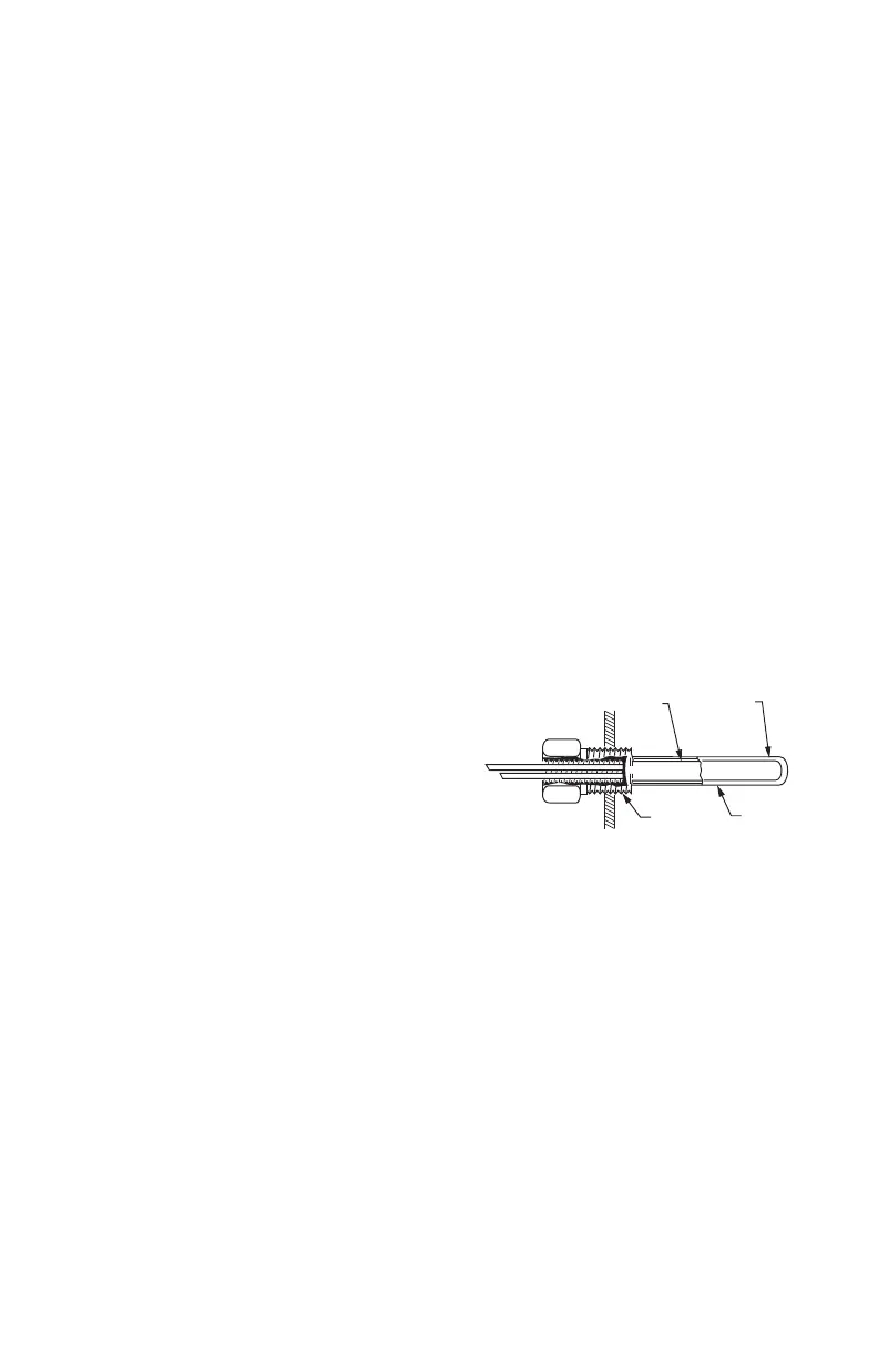
Fig. 2. Sensor Inserted in Immersion Well.
NOTE: Multiple sensors may be parallel-series wired
to sense average temperatures in large
spaces (Refer to Fig. 3 on page 4).
WIRING
All wiring must comply with applicable electrical codes
and ordinances, or as specified on installation wiring
diagrams. Controller wiring is terminated to the screw
terminal blocks located inside the device.
The remainder of this section describes the temperature
sensor wiring and the T775R controller wiring.
Wiring Connections Access
To access the wiring connections, remove the two screws
on the left side of the enclosure and gently swing open the
top. Be careful to not stress the ribbon cables that connect
the keypad and LCD display to the controller circuit board.
SENSOR
PLACED
IN WELL
IMMERSION
WELL
1/2 NPT
USE HEAT
CONDUCTIVE
COMPOUND
M24280

 Loading...