T775R SERIES 2000 ELECTRONIC STAND-ALONE CONTROLLER
62-0249—13 22
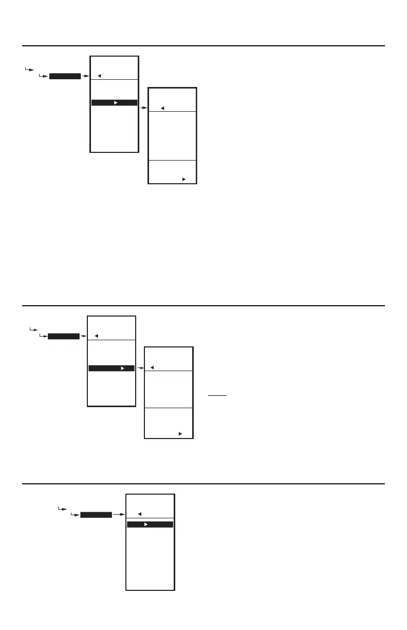
Fig. 52. Setup - Sensors - Sensor B - Hi/Low Limit
(showing Hi Limit).
3.2.3.3.1. HI LIMIT or LOW LIMIT (Sensor B
only)
Fig. 52 shows the Hi Limit, but the process is the same for
setting the Low Limit. This applies to the T775R2043
model only.
Sensor B can be assigned a high/low limit, so that as you
are controlling temperature at Sensor A, the control
adjusts its modulating output to prevent exceeding the
user-entered limit for Sensor B.
1. From the Sensor B menu, use the button to high-
light HI LIMIT or LOW LIMIT.
2. Press the button display the LIMIT value.
3. Use the and buttons to increase/decrease the
desired Limit value.
4. Press the button to accept the value and return to
the Limit menu.
The high and low limit action will work in either the heat or
cool mode as follows:
• When the low limit is used in the heat mode, the MOD1
output increases to prevent reaching the low limit at
sensor B.
• When the high limit is used in the heat mode, the
MOD1 output decreases to prevent reaching the hi
limit at sensor B.
• When the low limit is used in the cool mode, the MOD1
output decreases to prevent reaching the low limit at
sensor B.
• When the high limit is used in the cool mode, the
MOD1 output increases to prevent reaching hi limit at
sensor B.
Fig. 53. Setup - Sensors - Sensor B - Throttling Range.
3.2.3.4. THROTTLING RANGE (Sensor B
only)
The throttling range for the modulating high or low limit
positions the setpoint at the end of the throttling range.
For example, with a high limit at Sensor B of
200°F (93°C) and a throttling range of 10°F (-12°C), the
modulating output controlling Sensor A begins to throttle
back at 190°F (88°C), and fully closes at 200°F (93°C).
Conversely, the throttling range for the low limit begins
above
the setpoint in the same manner.
1. From the Limit menu, use the button to highlight
THROT RNG.
2. Use the and buttons to increase/decrease the
desired value for the Throttling Range.
Default = 0
3. Press the button to accept the value and return to
the Limit menu.
4. Press the button to exit the Limit menu.
5. Press the button to exit the Sensors menu and
return to the Setup menu.
Fig. 54. Setup - Outputs Menu.
3.3.3. Setting up the Outputs
1. From the Setup menu, use the and buttons to
highlight OUTPUTS.
2. Press the button to display the Outputs menu.
NOTE: The menus (e.g. the Outputs menu shown
here) can display only those relays that are
defined in Setup (Refer to “3.3.4. NBR OF
RELAYS” on page 25). For example, if you
configure only two relays, then only two
relays display on the appropriate menus.
The following procedures set up each modulating output
and relay output.
SETUP
SENSORS
SENSOR B
CALIBRATE
LABEL
LIMIT
HI LIMIT
THROT RNG
EXIT
SETUP
SENSORS
SENSOR B
ENTER
VALUE FOR
SENSOR B
HI LIMIT
SETUP
SENSORS
SENSOR B
HI LIM
90
F
o
M24331
SETUP
SENSORS
SENSOR B
CALIBRATE
LABEL
LIMIT
HI LIMIT
THROT RNG
EXIT
SETUP
SENSORS
SENSOR B
ENTER
VALUE FOR
SENSOR B
THROTLING
RANGE
SETUP
SENSORS
SENSOR B
THROT RNG
10
F
o
M24332A
SETUP
OUTPUTS
MOD 1
SETUP
OUTPUTS
MOD 1
TYPE
MIN OUT %
INTEGRAL
DERIVATIV
SCHEDULE
RESET
HIDE
EXIT
M24334A

 Loading...