4 Assembly
Rotary actuators 135 • M140 • M150 • M180
12 Version 2.0 - June 2012 Operating instructions
4.3 Mount rotary actuator on flap
If rotary actuator and flap are supplied as separate deliveries you will have to
mount the rotary actuator on the flap.
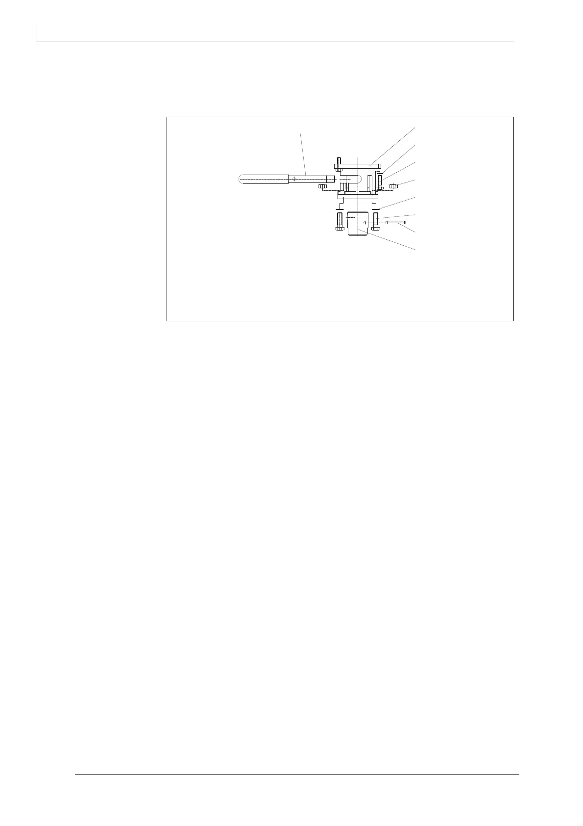
How to assemble a rotary actuator
1 Secure the coupling (6) to the actuator shaft with pins using the spiral pin (351)
2 Attach the knee (1) below the actuator with the four hexagon screws (426), using
spanner width 10 and thrust washers (306) applying a torque of 5 Nm.
3 Turn the hand lever (55) into the coupling (6).
4 Put the actuator with add-on kit on the flap.
5 Insert the four hexagon nuts (448) in the slots of the knee (1).
6 Insert the hexagon screws (428) spanner width 13 and slipped on thrust washers
(308)
from
below through the flap flange.
7 Connect the four hexagon screws (428) spanner width 13 to the hexagon nuts
(448) applying a torque of 7 Nm.
How to disassemble a rotary actuator
1 Follow the sequence of operation in reverse order.
1 Knee-Bracket
6 Coupling
55 Manual lever
306 Thrust washers
308 Thrust washers
351 Spiral clamping pin
426 Hexagon screws
428 Hexagon screws
448 Hexagon nuts
Fig. 7 Add-on kit for flaps