5 Commissioning
Rotary actuators 135 • M140 • M150 • M180
Operating instructions Version 2.0 - June 2012 21
5 Turn off the motor.
6 Turn the cam disk until the path switch switches.
7 Tighten the respective pair of screws.
8 Slip the pointer (64) on the shaft (12). Ensure that the pointer‘s locking pin
engages with the designated drilled hole in the shaft.
5.2 Setting the potential-free path switches
Set the two path switches separately. Try out the sequence of operations for each
path switch once.
Hint: The cam disks (45.1) to (45.4) inside the cam block (40) can be adjusted
separately. The pairs of screws are allocated to each cam ring by height.
How to set potential-free path switches
Risk of injury from electric shock by live parts!
When the supply voltage is turned on there is a risk of electric shock from live
parts.
• Take care not to touch any live parts.
1 Remove the hood (200).
4.4 Assembling/disassembling a hood on page 13
2 Pull off the pointer (64) off the shaft (45.1).
3 Remove the respective pair of screws.
4 Move the actuator, either manually or electrically, into the desired position.
5 Turn off the motor.
6 Turn the cam disk until the path switch switches.
7 Tighten the respective pair of screws.
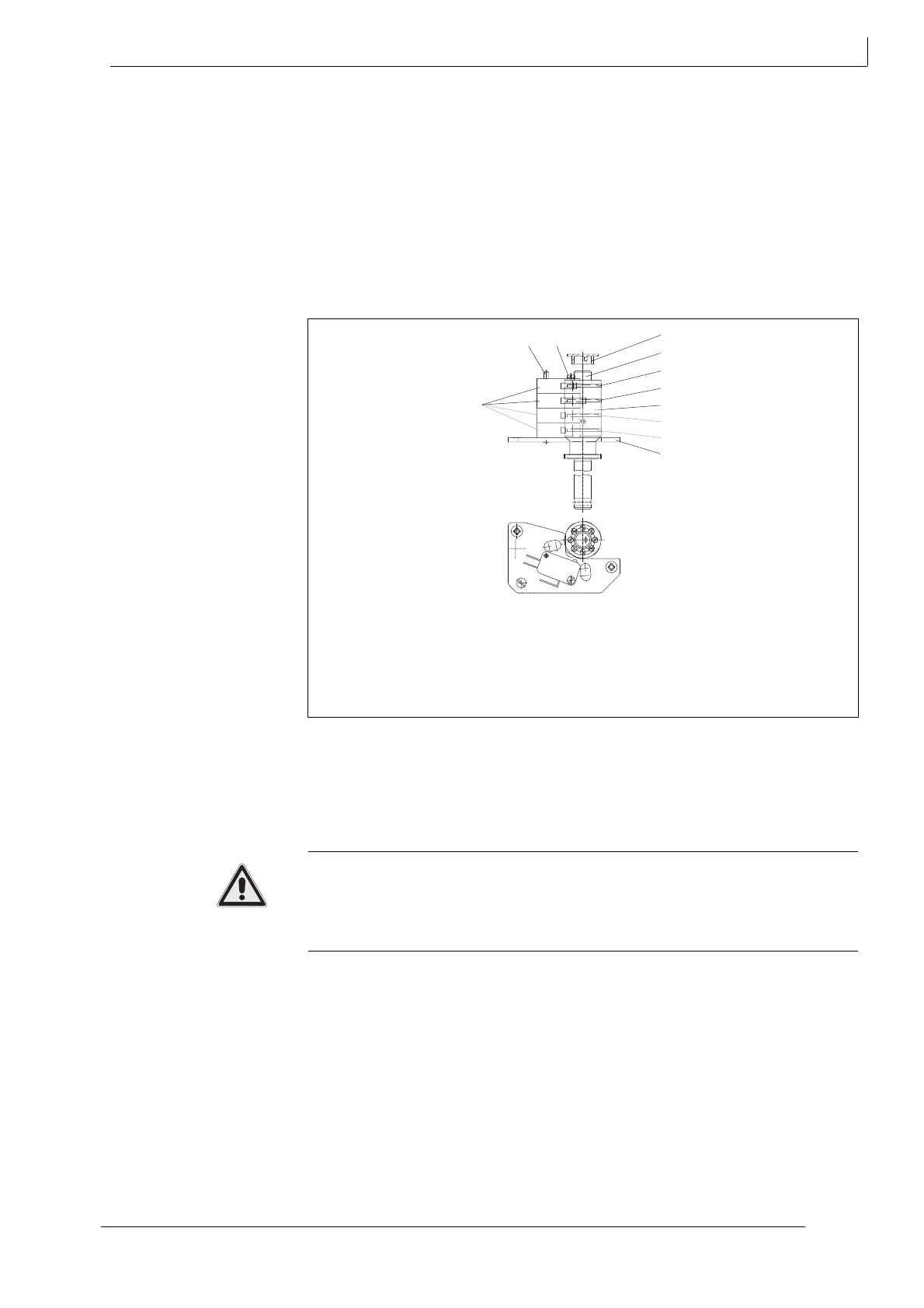
12 Shaft
40 Cam block
45.1Cam disk for WE 1
45.2Cam disk for WE 2
45.3Cam disk for WE 3
45.4Cam disk for WE 4
64 Pointer
106 Path switch / limit position switch
170 Path switch board
350 Pin
393 Slotted screw
Fig. 14 Setting path switches
WE
WE
106
350
393
64
12
45.4
45.3
40
45.2
45.1
170