4 Assembly
Rotary actuators 135 • M140 • M150 • M180
Operating instructions Version 2.0 - June 2012 17
4.6.2 Fitting a potentiometer
Risk of injury from electric shock by live parts!
When the supply voltage is turned on there is a risk of electric shock from live
parts.
• Prior to commencing any work, ensure that the actuator is safely discon
nected
fro
m the power supply system.
• Secure against unauthorised restarting.
1 Remove the hood (200).
4.4 Assembling/disassembling a hood on page 13
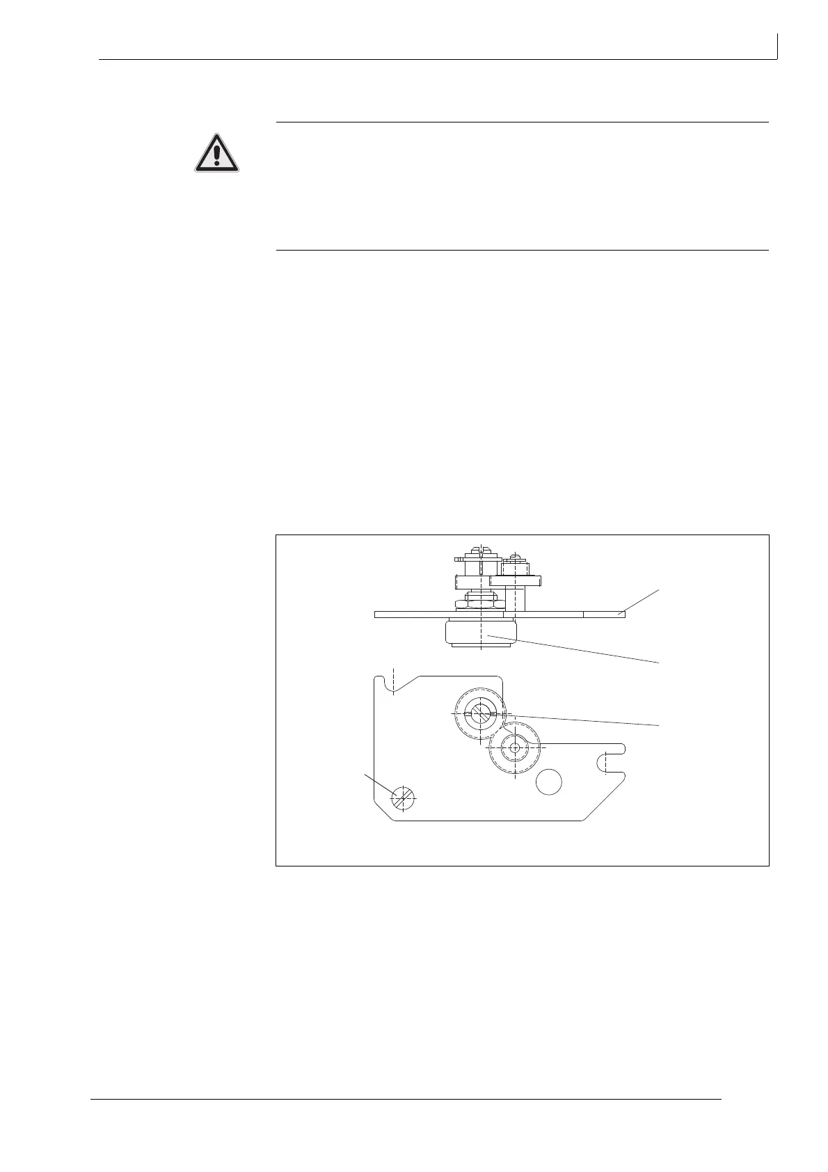
2 Attach the potentiometer board (180) with slits in the recess of the hexagon
sleeves underneath the path switch using slotted screw (394) M4 x 20 and thrust
washers.
Hint: Ensure correct meshing of gears.
3 Run the cable for the potentiometer to the angle bracket.
4 Secure the terminals of the path switch with the slotted screws on the angle
bracket at terminal designations 30, 31, 32.
Fig. 9 Wiring diagram on page 15
5 Set the potentiometer.
6 5.3 Setting a potentiometer on page 22
105 Potentiometer
180 Potentiometer board
394 Slotted screw
Fig. 11 Fitting a potentiometer