4 Assembly
Rotary actuators 135 • M140 • M150 • M180
16 Version 2.0 - June 2012 Operating instructions
4.6 Fitting accessories
Accessories are not part of the scope of delivery for the rotary actuator unless
expressly ordered! The rotary actuators are prepared for retro-fitting with:
• Path switch (106)
• Potentiometer (180)
• Actuator heater (190)
2.2 Accessories on page 7
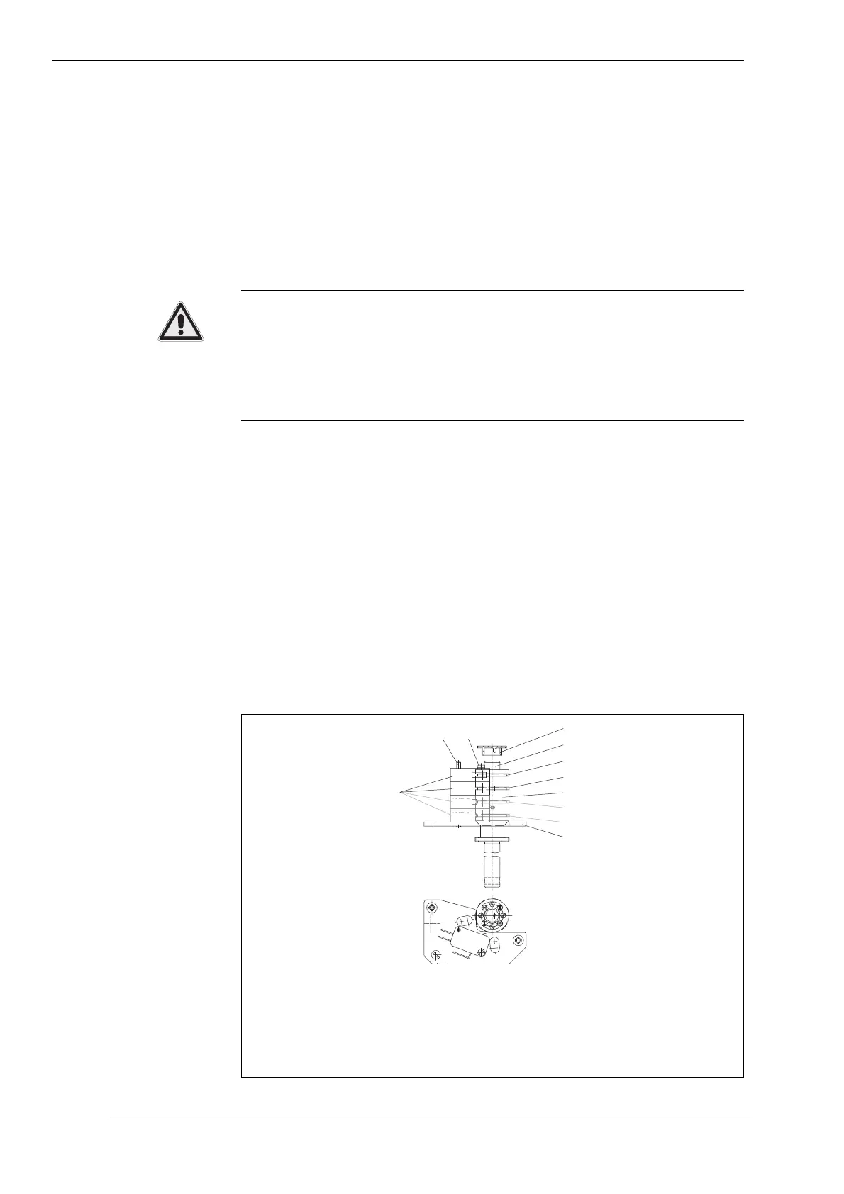
4.6.1 Fitting path switches WE 3 and WE 4
Risk of injury from electric shock by live parts!
When the supply voltage is turned on there is a risk of electric shock from live
parts.
• Prior to commencing any work, ensure that the actuator is safely disconnected
from the power supply system.
• Secure against unauthorised restarting.
1 1 Remove the hood (200).
4.4 Assembling/disassembling a hood on page 13
2 Remove slotted screw M3 x 25 (393) and thrust washer.
3 Put path switches WE 3 (45.3) and WE 4 (45.4) on pin (350).
4 Secure path switches WE 3 (45.3) and WE 4 (45.4) with slotted screw M3 x 45
(393)
an
d thrust washer.
5 Run the cables for the path switches to the angle bracket.
6 Secure the terminals for the pacam diskth switches with the slotted screws on
the angle bracket at terminal designations 20, 21, 22 and 23, 24, 25.
Fig. 9 Wiring diagram on page 15
7 Set the path switches.
5.2 Setting the potential-free path switches on page 21
12 Shaft
40 Cam block
45.1Cam disk for WE 1
45.2Cam disk for WE 2
45.3Cam disk for WE 3
45.4Cam disk for WE 4
64 Pointer
106 Path switch / limit position switch
170 Path switch board
350 Pin
393 Slotted screw
Fig. 10 Fit path switch
WE
WE
106
350
393
64
12
45.4
45.3
40
45.2
45.1
170