4 Assembly
Rotary actuators 135 • M140 • M150 • M180
Operating instructions Version 2.0 - June 2012 15
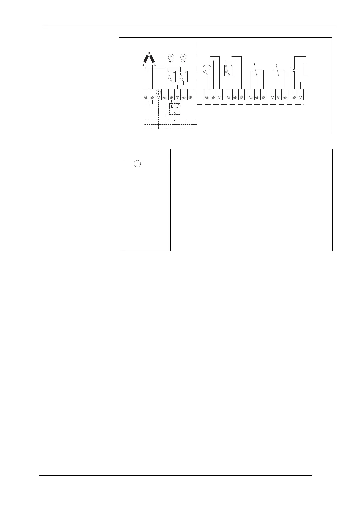
Fig. 9 Wiring diagram
Terminal Description
PE / Protective conductor
N1 Supply voltage:
2 Control voltage for rotary motion anti-clockwise
3 Control voltage for rotary motion clockwise
20, 21, 22 Terminals path switch unit WE 3
23, 24, 25 Terminals path switch unit WE 4
30, 31, 32 Terminals potentiometer P1
33, 34, 35 Terminals second potentiometer P2
40, 41 Terminals actuator heater
table 2 Key to wiring diagram
40
41
30
31
32
33
34
35
20
21
22
23
24
25
N1
WE 1 WE 2 WE 3 WE 4 P1 P2 H
L
N
PE