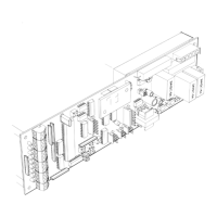
BELT DRIVE
TS 1
Lock Failure (Fail Safe ) Indicates that the lock solenoid failed to move
the plunger enough to activate the lock monitor switch.
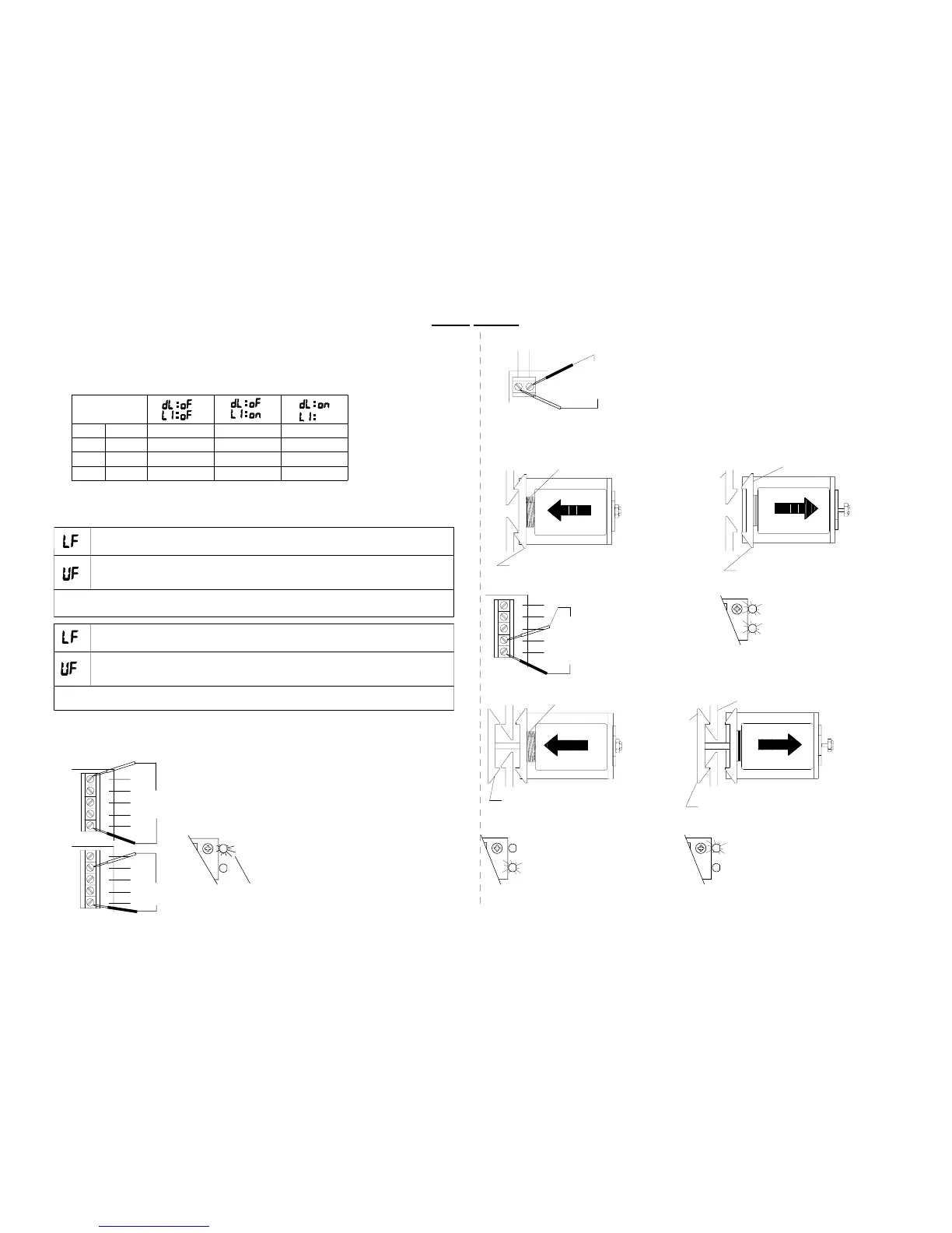
NOTE: The terminal strips TS1 & TS2
are located on the autolock
Basic voltage readings regardless of type.Set VOM at 200VDC.
Unlock Failure (Fail Safe ) Indicates that the lock solenoid spring has failed
to move the plunger enough to activate the lock monitor switch and notify the control that
the door is ready to be opened.
Check for mechanical binding. Check items under AUTOLOCK TEST POINTS and
AUTOLOCK FUNCTIONS FOR FAIL SAFE autolocks.
-There should always be a supply voltage of
25 to 33 VDC between pins 1 and 5 at TS 1.
-When the control's orange lock light is on there
should be 3 to 5 VDC between pins 2 and 5 at TS 1.
19. AUTOLOCK TEST POINTS
TS 1
RE D
1
2
2.0478d
BL K
WH T
GRN
RED
BRN
BL K
WHT
GR N
2
3
1
TS 1
4
5
4
3
5
09-07
LOCK
MON
LOCK
O
Y
BR N
To set up the lock parameters on the C2150 turn off the toggle circuit or double click the
SET button. Use the UP / DOWN buttons to locate dL & L1.
Press the set button to display the on or off setting. Set dL / L1 as required from the table
below.
SEE SECTION 3 STEP 10 FOR ( ds ) DATA SAVE PROCEDURE
Unlock Failure (Fail Secure ) Indicates that the lock solenoid failed to move
the plunger enough to activate the lock monitor switch and notify the control
that the door is ready to be opened.
Lock Failure (Fail Secure ) Indicates that the lock monitor input is remaining
active (lock monitor light is still on) even though solonoid has de-energized.
Check for mechanical binding. Check items under AUTOLOCK TEST POINTS and
AUTOLOCK FUNCTIONS FOR FAIL SECURE autolocks.
Locked
17. SETTING LOCK PARAMETERS
Locked
Unlocked
Locked
2-Way
Locked
Nite
Locked
Nite
1-Way
18. LOCK ERROR CODES
Unlocked
Unlocked
Traffic Mode
Day
1-Way
Day
2-Way
Locked
Locked
Locked
doesn't
matter
Locked
When the lock is unplugged and
the solenoid manualy depressed
there should be continuity between
pins 4 and 5 of TS1
The yellow lock monitor
and the orange lock LED's
should both be lit when the
solenoid is retracted.
H210.11
When the lock is unplugged and the solenoid is
not
manually depressed there should be
continuity between pins 4 and 5 of TS1. Check the jumpers on the
Autolock circuit board. (see section 6)
The FAIL SAFE is a less common type of auto lock used with the C2150.
When power is applied the solenoid
is retracted and the door is locked.
top view unlocked
The yellow lock monitor
LED is lit when the solenoid is
not
retracted.
LOCK
LOCK
MON
Y
O
When power is removed the solenoid
is extended by the lock spring. The
door is unlocked.
SOLENOID
5
Lock spring
4
BLK
WHT
Lock hooks
3
GRN
top view locked
The orange lock LED is lit
when the solenoid is retracted.
O
LOCK
MON
Y
LOCK
SOLENOID
Door panel hooks
Y
The FAIL SECURE is the most common type of auto lock used with the C2150.
20. AUTOLOCK FUNCTIONS
-When the solenoid initially energizes there
should be 25 to 33 VDC at TS2.
After about a second the voltage will drop
to about 30% of the supply voltage between pins
1and2ofTS2 .
Lock spring
When power is removed, the solenoid
is extended by the lock spring. The
door is locked.
1
2
SOLENOIDSOLENOID
BRN
top view locked
No LED's are lit
RED
TS 2
BLK
BLK
Lock hooks
Door panel hooks
LOCK
O
LOCK
MON
top view unlocked
When power is applied the solenoid
is retracted and the door is unlocked.
SOLENOID
 Loading...
