EasyManuals Logo

Horton C2150 User Manual

Horton C2150
23 pages
To Next Page IconTo Next Page
To Previous Page IconTo Previous Page
Page #22 background imageLoading...
Page #22 background image
Gray shield (13)
Emitter Gray wire (12)
Gray shield (11)
Emitter Gray wire (10)
Blue sheild (9)
Receiver Blue wire (8)
DIAGRAM 2 TYPICAL WIRING for BEAMS and SWITCHES
Locate the beam
amplifier as close to
the C2150 as possible
Optex OS10-c 2 channel photo electric system (standard wiring with amplifier)
2000
HEADER MOUNT
Typical Bi-part
2.0487d
07-09
C437 A/B
Drill #10 & csk
for #10 screw
1.38"
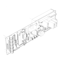
C2150
2003 - use left
hand slot
Secure the board to the
bracket with C1616-1
VHB tape (1" strip)
C1089
2003
HEADER MOUNT
2001 SIM.
C1089
NOTE:
Mount board low
enough to allow
space for the nut &
washer.
Blue sheild (7)
Receiver Blue wire (6
)
2001 - use right
hand slot
H210.20
Wiring connections
Typical Single slide
Blue wire
Receiver
C2150
wire
shield
5/8"
Press down release
and insert wire & shield
Emitter
Strip wires 5/16"
(5)Blk -24 VDC
(6)Red -safety beam
(7)Wht -common
(7)Grn -common
Amplifier
Header lace
Gray wire
Emitter
C1089
Bracket
(5)Red
(4)Grn
(2)Wht
(1)Blk
Gray wire
Receiver
Blue wire

Other manuals for Horton C2150

Questions and Answers:

Question and Answer IconNeed help?

Do you have a question about the Horton C2150 and is the answer not in the manual?

Horton C2150 Specifications

General IconGeneral
BrandHorton
ModelC2150
CategoryController
LanguageEnglish