BELT DRIVE
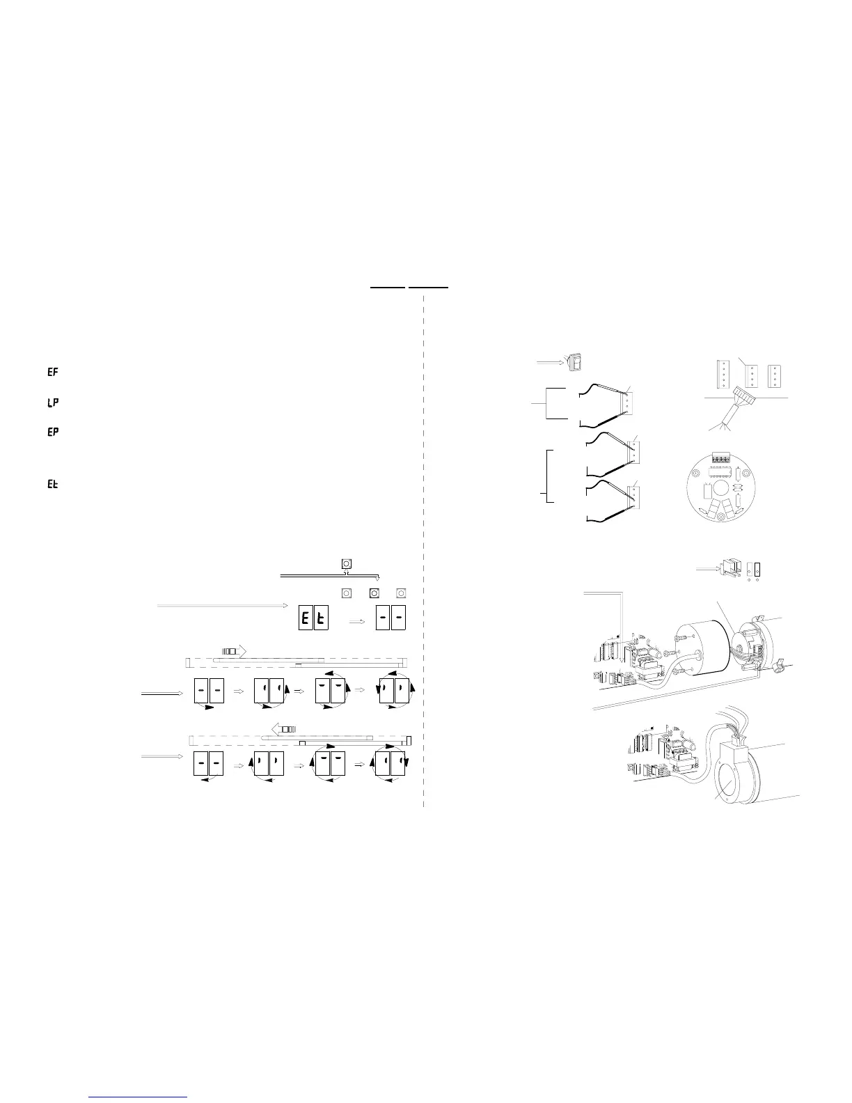
Encoder Phasing - Encoder indicates door is moving opposite direction it should be.
-Power brackets are connected to the belt backwards
(see appendix F)
-Wires should be reversed at terminal 2 & 3 on the encoder
on C5600 & C3675 only.
Each segment of 4 for a total of 8 segments should appear. No segment should be skipped.
If anything occurs other than the description shown above the C2150 will get improper
information and the door will not function properly.
Encoder error codes are displayed when the door is running. Normally codes will be
displayed at the end of a stroke or when a door stops abruptly during an "open"
command.
Encoder Test - The beginning of an encoder test procedure.
-See section below
Loss of Pulses - All pulses required for proper operation were not received.
-See encoder test points Section 13
Encoder Failure - No pulses being received by the C2150.
Encoder information is needed to provide consistent information on location, direction
of travel, speed of door and door braking information to the C2150 control.
-Press RESET and the DOWN button together
-Release RESET and continue to hold the DOWN button
until ET briefly appears - release the DOWN button.
Following ET 2 short lines will appear. The test
is ready to be performed.
1st Step - Encoder test
2.0479d
09-07
Manually move the door towards
the closed position.
The display will show a clockwise
rotation.
View the display while manually
moving the door slowly towards the
open position.
The display will show a counter
clockwise rotation.
2nd Step - Performing test
Close direction
Then
Open direction
SET
DOWN
UP
21. ENCODER ERROR CODES
-Check all connections to encoder and the control.
Types of failure codes that could be displayed:
22. ENCODER DIAGNOSTICS
RESET
-Check JB 1. This circuit should be open - jumpers off as shown.
H210.12
Checking connections
-Check the depth of the encoder wheel as it
passes through the encoder optics.
-If all visual inspections pass, the encoder
board may have failed. Remove and replace.
See appendix E
-Check the rotation of the encoder wheel
as the door is moved manually.
There are no serviceable elements on the C5600-1.
If the encoder fails replace the entire unit. DO NOT REMOVE COVER
CN 1
-Confirm that the encoder is pluged into CN1 and that
the wires are connected to the plug.
On the C5600 & C3675 only
-Remove the encoder cover and check
that all wiring is secured in the terminal
block.
There is power between pins 1 & 4 but
there is no pulse between 2 & 4
or 3 & 4.
Power but no pulse
CN 1
C5600-1
2003
C3675
2001 (sim)
Encoder wheel
C5600
2003
23. ENCODER TEST POINTS
CN 1
5VoltsDC
(pulse)
5VoltsDC
(constant)
5VoltsDC
(pulse)
To test the encoder you will need a volt ohm meter (VOM) capable of reading DC Voltage.
If the above voltages check out and the display does not rotate as shown
in section 12 then contact the technical services group.
-To verify the encoder is
producing pulses slowly
move the door manually
with the meter attached
to2&4then3 & 4.
Watch the meter for 5 volt
pulses.
-Turn the toggle circuit off.
-Probe through the back
of the red plug leaving it
attached to CN 1.
-Set the VOM to 200 DCV
Checking power and pulses
4-BLK
GRN-2
RED-1
WHT-3
BLK-4
4 3 2 1
CN 1
4-BLK
3-WHT
4-BLK
2-GRN
CN 1
GND
1
CN 1
1-RED
 Loading...
