30
C. Control Board Check
Before replacing a control board that does not show a visible defect and that you suspect
is bad, always conduct the following check procedure. This procedure will help you
verify your diagnosis. Before proceeding, check for proper voltage per unit nameplate.
Check that the 24VAC 1A fuse and the 115VAC 3A GM fuse are good. When checking
for high-voltage (115VAC), always choose a white (W) neutral wire to establish a good
neutral connection. When checking for low-voltage (secondary) (24VAC), always choose
a light blue (LBU) neutral wire to establish a good neutral connection. If the icemaker is in
alarm,see"II.C.2.LEDLightsandAudibleAlarmSafeties."
Note:EHenergizeswhen"GM"LEDturnson.CBX1ComprelayenergizesPDS.
Refrigeration circuit low-side pressure rises to 29 PSIG, closing the CLPS
contacts. MC is energized when CLPS closes, energizing Comp and FMR.
1) Check the S1 dip switch settings to assure that they are in the factory default position.
Forfactorydefaultsettings,see"II.C.3.a)DefaultDipSwitchSettings."S1 dip switch
7determines bin control application:
Bin Control Application:
Infrared Sensor Bin Control with Mechanical Backup Bin Control: S1 dip switch
7inthe"ON"position.
Mechanical Bin Control (Standard Ice Storage Bin):S1dipswitch7inthe"OFF"
position.
2) Startup – "POWER OK" LED on:Movethecontrolswitchtothe"ICE"position,
thenmovethepowerswitchtothe"ON"position.The"POWEROK"LEDturnson.
Diagnosis "POWER OK" LED:Checkthatthe"POWEROK"LEDison.Ifnot,
check for proper supply voltage (115VAC) input to the CT (main breaker or fuse and
power switch). Next, check for proper low-voltage (24VAC) output from CT and that
the 1A fuse is good. Check for 24VAC from K8 connector pin #1 white/red (W/R) to
K8connectorpin#2lightblue(LBU).If24VACispresentandthe"POWEROK"LEDis
off, CB is bad and must be replaced.
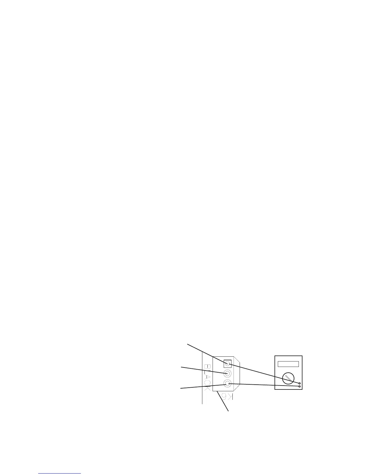
3) IS Power Supply: CB supplies 20VDC to IS. Diagnosis: Check that IS green LED is
on. If green LED is not on, check for 20VDC between CB connector K6dark blue (DBU)
and connector K6brown(BR). See Fig. 1. If 20VDC is not present, CB is bad and must
be replaced.
Fig. 1
Red Positive
Test Lead
Black Negative
Test Lead
20VDC
Multimeter
Infrared Sensor (20VDC)
Open(yellowLEDashingorsteady)
20VDC DBU to BR
0VDC DBU to W
20VDC W to BR
Infrared Sensor (20VDC)
Closed
20VDC DBU to BR
20VDC DBU to W
0VDC W to BR
Brown (BR)
Dark Blue (DBU)
White (W)
•K6 Connector
Infrared Sensor
 Loading...