53
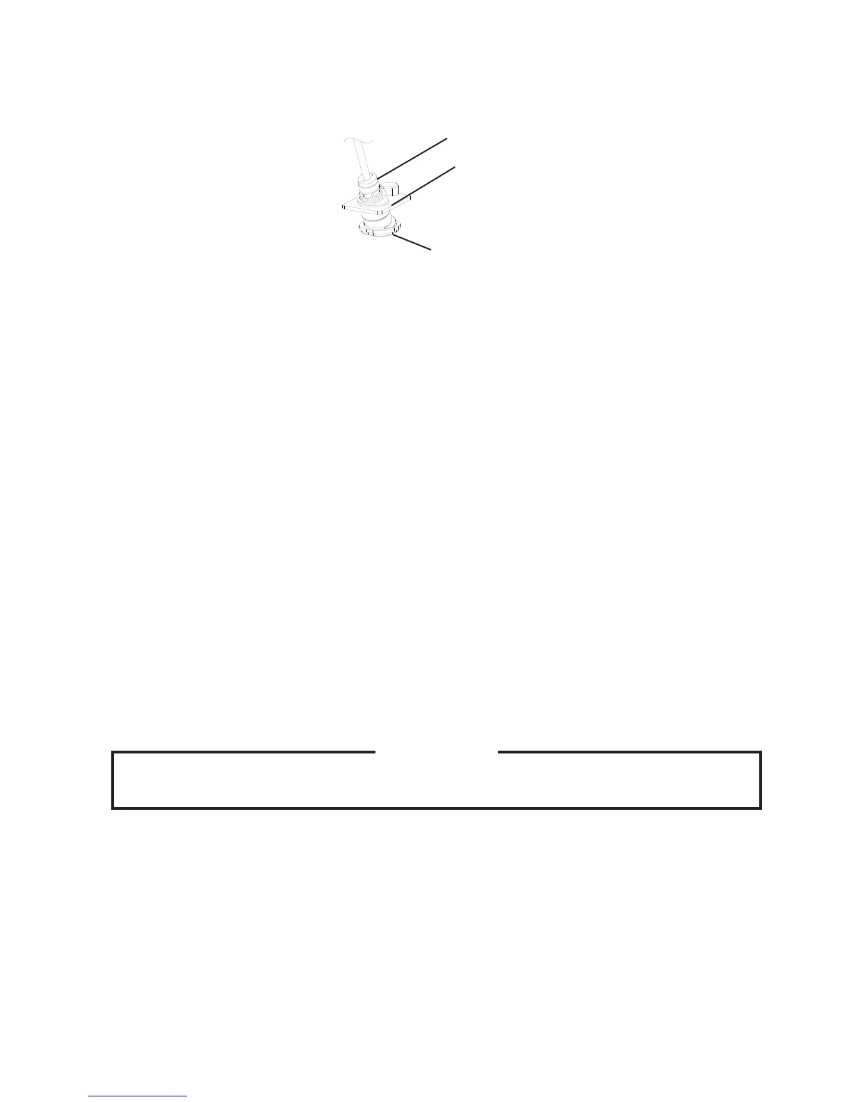
11) Wipe down the infrared sensor lens, (located on the bottom of the icemaker) with the
cleaning solution. Next, rinse the cleaning solution off of the infrared sensor lens with a
clean, damp cloth.
Infrared Sensor
Infrared Sensor
Housing
Lens
12)Replacethetoppanelinitscorrectposition.Movethecontrolswitchtothe"ICE"
position,thenplugtheunitbackin.Movethepowerswitchtothe"ON"position,then
replace the front panel in its correct position. Make ice using the solution until the
icemaker stops making ice.
13)Removethefrontpanel,thenmovethepowerswitchtothe"OFF"position.Movethe
controlswitchtothe"DRAIN"position,thenmovethepowerswitchbacktothe"ON"
position. Replace the front panel in its correct position.
14) Allow the water system to drain for 5 minutes.
15)Removethefrontpanel.Movethecontrolswitchtothe"ICE"position,thenreplacethe
front panel in its correct position.
16) Open the water supply line shut-off valve to supply water to the reservoir.
17)Afterthegearmotorstarts,removethefrontpanel.Movethepowerswitchtothe"OFF"
position.Movethecontrolswitchtothe"DRAIN"position,thenmovethepowerswitch
backtothe"ON"position.Replacethefrontpanelinitscorrectposition.
18) Allow the water system to drain for 5 minutes.
Note:Ifyoudonotsanitizetheunit,gotostep14in"III.A.5.Sanitizing
Procedure-Final."
19)Removethefrontpanel.Movethepowerswitchtothe"OFF"position,thenunplugthe
unit from the electrical outlet. Close the water supply line shut-off valve.
3. Sanitizing Solution
IMPORTANT
For safety and maximum effectiveness, use the solution immediately after
dilution.
Dilute2.5.oz.(74mlor5tbs)ofa5.25%sodiumhypochloritesolution(chlorinebleach)
with 5 gal. (19 l) of warm water.
4. Sanitizing Procedure - Initial
1)Makesurethepowerswitchisinthe"OFF"position,theunitisunpluggedfromthe
electrical outlet, and the water supply line shut-off valve is closed. Remove the panels.
2) Remove the strap connecting the spout to the chute assembly, then remove the spout.
Remove the rubber O-ring and nylon O-ring at the top of the cylinder and also remove
the packing and chute bracket between the spout and chute.
Fig. 14
 Loading...