37
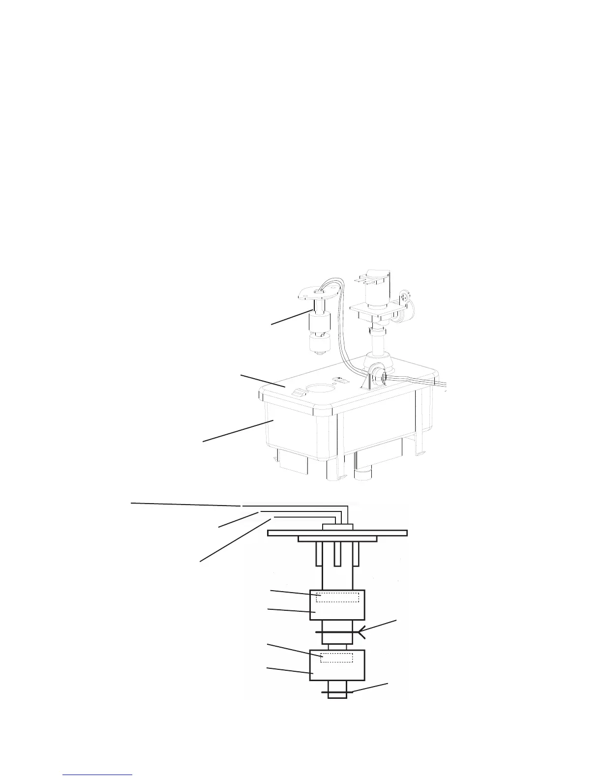
Reservoir
Reservoir Cover
Float Switch Assembly
Red (R)
(upperoatswitch)
Black (BK)
(common)
Dark Blue (DBU)
(loweroatswitch)
Upper Float (blue)
Magnet (towards top)
Magnet (towards top)
Lower Float (white)
Plastic Retainer Clip
Spring Retainer Clip
Fig. 5
Fig. 6
3)WipedownF/Sassemblywithamixtureof1partHoshizaki"ScaleAway"and25parts
warm water. Rinse the assembly thoroughly with clean water.
4)Whilenotnecessary,theoatscanberemovedfromtheshaftduringcleaning.Ifyou
removethem,notethattheblueoatisontop(UF/S)andthewhiteoatisonbottom
(LF/S).Theoatsmustbeinstalledwiththemagnetsinsidethemtowardsthetopof
theswitch.SeeFig.6.InstallingtheoatsupsidedownwillaffectthetimingofF/S
operation.
5)Rinsetheoatswitchassemblythoroughlywithcleanwaterandreplaceinitscorrect
position.
6)Plugtheunitintotheelectricaloutlet,thenmovethepowerswitchtothe"ON"position
to start the automatic icemaking process.
7) Replace the front panel in its correct position.
Legend: CB–control board; F/S–oatswitch;GM–gear motor; LF/S–loweroatswitch;
UF/S–upperoatswitch
 Loading...