128
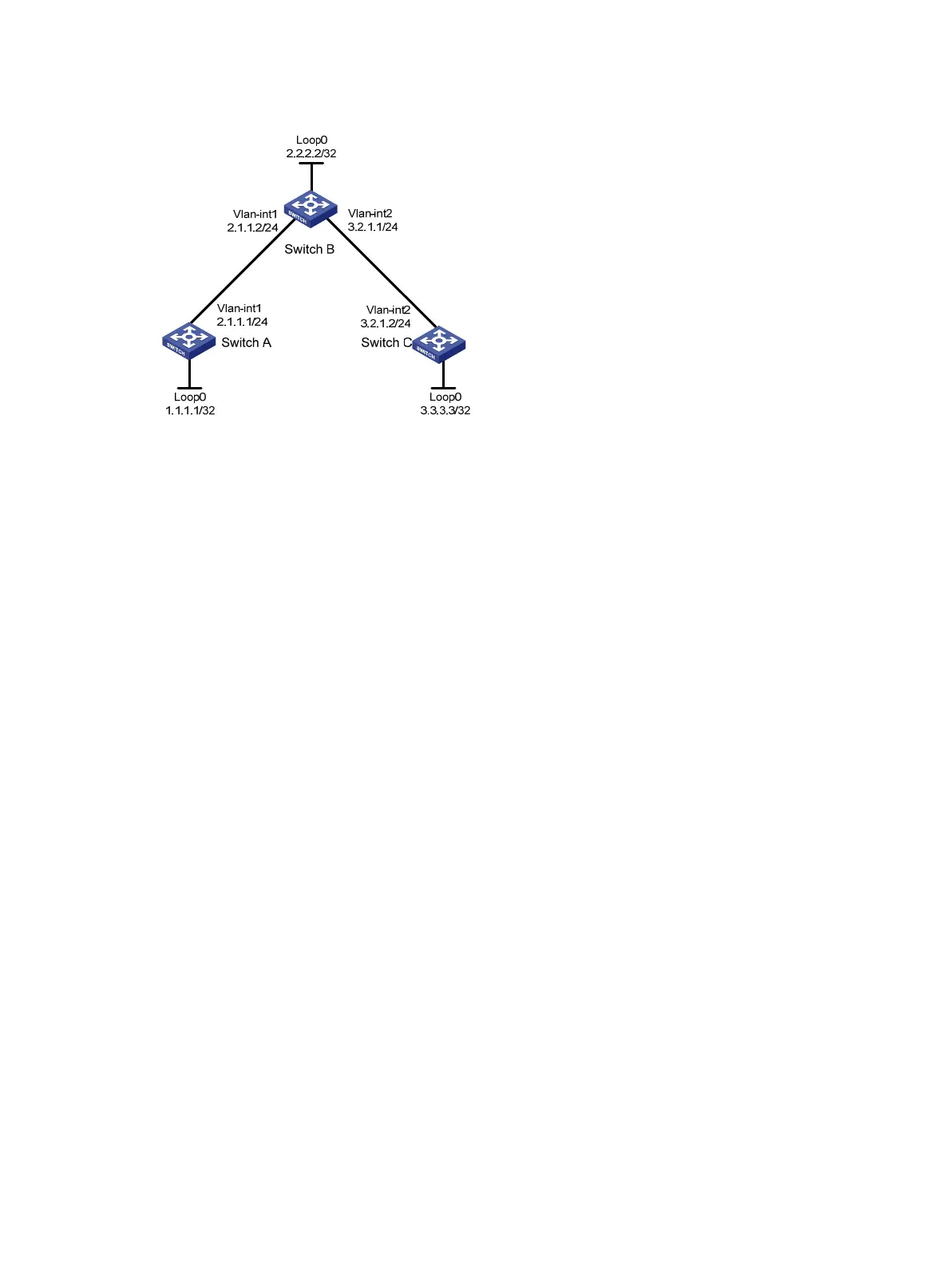
Figure 31 Network diagram
Configuration procedure
1. Configure IP addresses and masks for interfaces according to Figure 31. (Details not shown.)
2. Enable IS-IS to advertise host routes with LSR IDs as destinations:
# Configure Switch A.
<SwitchA> system-view
[SwitchA] isis 1
[SwitchA-isis-1] network-entity 00.0005.0000.0000.0001.00
[SwitchA-isis-1] quit
[SwitchA] interface vlan-interface 1
[SwitchA-Vlan-interface1] isis enable 1
[SwitchA-Vlan-interface1] quit
[SwitchA] interface loopback 0
[SwitchA-LoopBack0] isis enable 1
[SwitchA-LoopBack0] quit
# Configure Switch B.
<SwitchB> system-view
[SwitchB] isis 1
[SwitchB-isis-1] network-entity 00.0005.0000.0000.0002.00
[SwitchB-isis-1] quit
[SwitchB] interface vlan-interface 1
[SwitchB-Vlan-interface1] isis enable 1
[SwitchB-Vlan-interface1] quit
[SwitchB] interface vlan-interface 2
[SwitchB-Vlan-interface2] isis enable 1
[SwitchB-Vlan-interface2] quit
[SwitchB] interface loopback 0
[SwitchB-LoopBack0] isis enable 1
[SwitchB-LoopBack0] quit
# Configure Switch C.
<SwitchC> system-view
[SwitchC] isis 1

 Loading...


