146
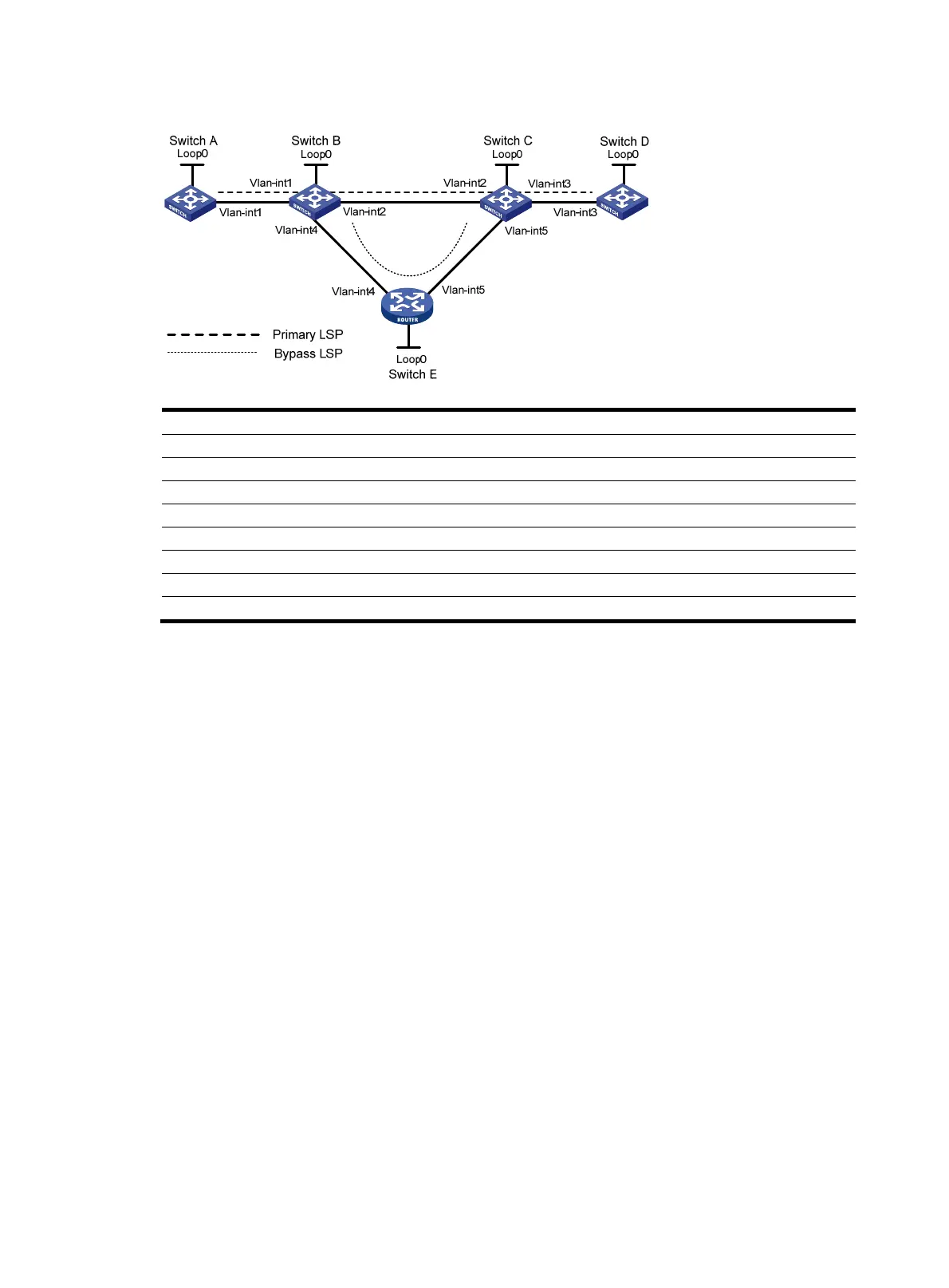
Figure 36 Network diagram
Device Interface IP address
Device
Interface
IP address
Switch A Loop0 1.1.1.1/32 Switch E Loop0 5.5.5.5/32
Vlan-int1 2.1.1.1/24
Vlan-int4
3.2.1.2/24
Switch B Loop0 2.2.2.2/32
Vlan-int5
3.3.1.1/24
Vlan-int1 2.1.1.2/24 Switch C Loop0 3.3.3.3/32
Vlan-int2 3.1.1.1/24
Vlan-int3
4.1.1.1/24
Vlan-int4 3.2.1.1/24
Vlan-int2
3.1.1.2/24
Switch D Loop0 4.4.4.4/32 Vlan-int5 3.3.1.2/24
Vlan-int3 4.1.1.2/24
Configuration procedure
1. Configure IP addresses and masks for interfaces according to Figure 36. (Details not shown.)
2. Configure the IGP protocol.
# Enable IS-IS to advertise host routes with LSR IDs as destinations on each node. (Details not
shown.)
# Execute the display ip routing-table command on each switch. You can see that all nodes have
learned the host routes of other nodes with LSR IDs as destinations. Take Switch A for example:
<SwitchA> display ip routing-table
Routing Tables: Public
Destinations : 13 Routes : 13
Destination/Mask Proto Pre Cost NextHop Interface
1.1.1.1/32 Direct 0 0 127.0.0.1 InLoop0
2.1.1.0/24 Direct 0 0 2.1.1.1 Vlan1
2.1.1.1/32 Direct 0 0 127.0.0.1 InLoop0
2.2.2.2/32 ISIS 15 10 2.1.1.2 Vlan1
3.1.1.0/24 ISIS 15 20 2.1.1.2 Vlan1
3.2.1.0/24 ISIS 15 20 2.1.1.2 Vlan1
3.3.1.0/24 ISIS 15 30 2.1.1.2 Vlan1
3.3.3.3/32 ISIS 15 20 2.1.1.2 Vlan1
4.1.1.0/24 ISIS 15 30 2.1.1.2 Vlan1
4.4.4.4/32 ISIS 15 30 2.1.1.2 Vlan1
5.5.5.5/32 ISIS 15 20 2.1.1.2 Vlan1
127.0.0.0/8 Direct 0 0 127.0.0.1 InLoop0

 Loading...


