335
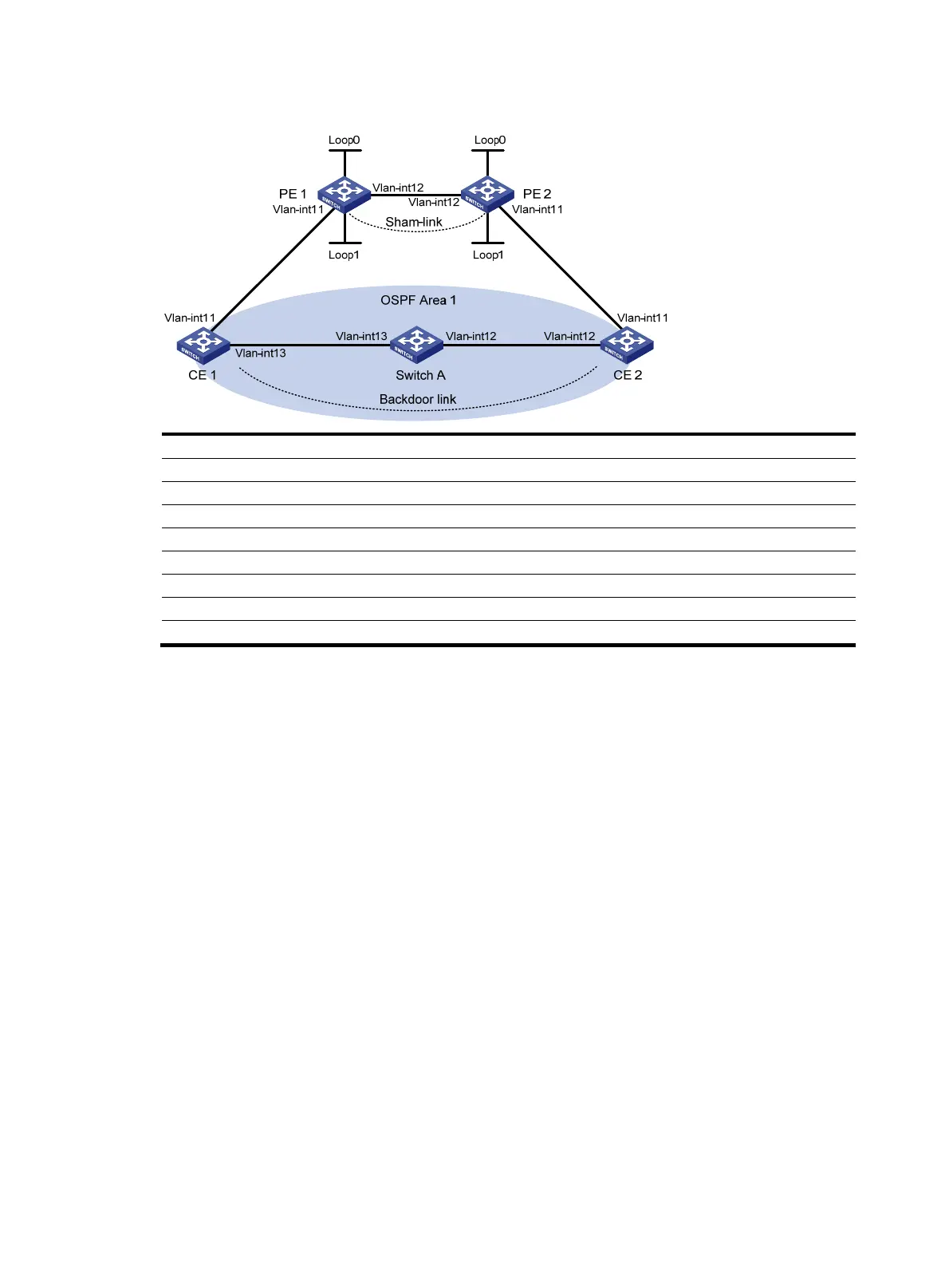
Figure 40 Network diagram
Device Interface IP address Device Interface IP address
CE 1 Vlan-int11 100.1.1.1/24
CE 2
Vlan-int11 120.1.1.1/24
Vlan-int13 20.1.1.1/24
Vlan-int12 30.1.1.2/24
PE 1 Loop0 1.1.1.9/32 PE 2 Loop0 2.2.2.9/32
Loop1 3.3.3.3/32
Loop1
5.5.5.5/32
Vlan-int11 100.1.1.2/24
Vlan-int11 120.1.1.2/24
Vlan-int12 10.1.1.1/24 Vlan-int12 10.1.1.2/24
Switch A Vlan-int11 20.1.1.2/24
Vlan-int12 30.1.1.1/24
Configuration procedure
1. Configure OSPF on the customer networks:
# Configure conventional OSPF on CE 1, Switch A, and CE 2 to advertise subnet addresses of the
interfaces as shown in Figure 40. (Details not shown.)
# After
completing the configurations, CE 1 and CE 2 can learn the OSPF route to the VLAN
interface 1 of each other. Take CE 1 as an example:
<CE1> display ip routing-table
Routing Tables: Public
Destinations : 9 Routes : 9
Destination/Mask Proto Pre Cost NextHop Interface
20.1.1.0/24 Direct 0 0 20.1.1.1 Vlan13
20.1.1.1/32 Direct 0 0 127.0.0.1 InLoop0
20.1.1.2/32 Direct 0 0 20.1.1.2 Vlan13
30.1.1.0/24 OSPF 10 3124 20.1.1.2 Vlan13
100.1.1.0/24 Direct 0 0 100.1.1.1 Vlan11
100.1.1.1/32 Direct 0 0 127.0.0.1 InLoop0
120.1.1.0/24 OSPF 10 3125 20.1.1.2 Vlan13
127.0.0.0/8 Direct 0 0 127.0.0.1 InLoop0
127.0.0.1/32 Direct 0 0 127.0.0.1 InLoop0
2. Configure MPLS L3VPN on the backbone:
# Configure basic MPLS and MPLS LDP on PE 1 to establish LDP LSPs.
<PE1> system-view

 Loading...


