340
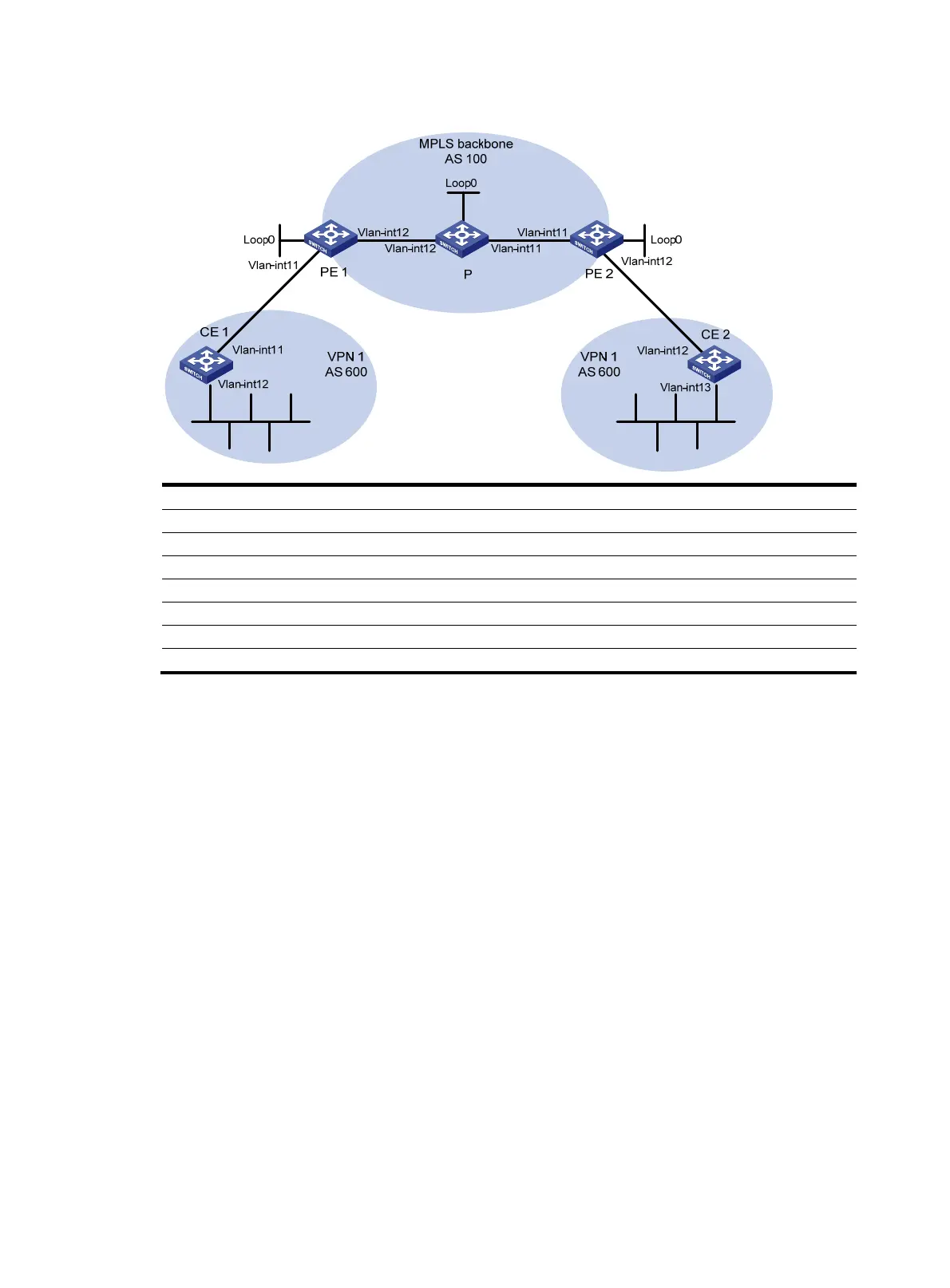
Figure 41 Network diagram
Device Interface IP address
Device
Interface
IP address
CE 1 Vlan-int11 10.1.1.1/24 P Loop0 2.2.2.9/32
Vlan-int12 100.1.1.1/24
Vlan-int11 30.1.1.1/24
PE 1 Loop0 1.1.1.9/32
Vlan-int12 20.1.1.2/24
Vlan-int11 10.1.1.2/24 PE 2 Loop0 3.3.3.9/32
Vlan-int12 20.1.1.1/24
Vlan-int11 30.1.1.2/24
CE 2 Vlan-int12 10.2.1.1/24
Vlan-int12 10.2.1.2/24
Vlan-int13 200.1.1.1/24
Configuration procedure
1. Configuring basic MPLS L3VPN:
{ Configure OSPF on the MPLS backbone to allow the PEs and P device to learn the routes of the
loopback interfaces from each other.
{ Configure basic MPLS and MPLS LDP on the MPLS backbone to establish LDP LSPs.
{ Establish MP-IBGP peer relationship between the PEs to advertise VPN IPv4 routes.
{ Configure the VPN instance of VPN 1 on PE 2 to allow CE 2 to access the network.
{ Configure the VPN instance of VPN 1 on PE 1 to allow CE 1 to access the network.
{ Configure BGP between PE 1 and CE 1, and between PE 2 and CE 2 to inject routes of CEs into
PEs.
After completing the configurations, execute the display ip routing-table command on CE 2. You
can see that CE 2 has learned the route to network 10.1.1.0/24, where the interface used by CE
1 to access PE 1 resides, but it has not learned the route to the VPN (100.1.1.0/24) behind CE 1.
The situation on CE 1 is similar.
<CE2> display ip routing-table
Routing Tables: Public
Destinations : 8 Routes : 8
Destination/Mask Proto Pre Cost NextHop Interface
10.1.1.0/24 BGP 255 0 10.2.1.2 Vlan11
10.1.1.1/32 BGP 255 0 10.2.1.2 Vlan11

 Loading...


