1-16
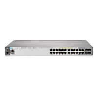
Introducing the HP 2920 Switches
HP 2920 10G Expansion Modules
10G Expansion Module LEDs
The following LEDs are located on the bulkheads of the HP 2920 10G Modules.
These LEDs are only viewable in the rear of the switch on the module itself.
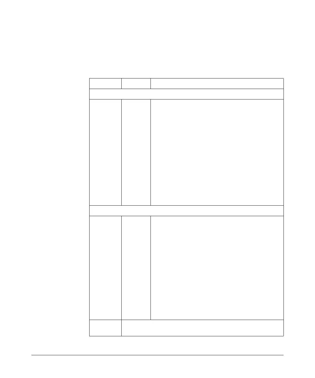
Table 1-5. 10G Expansion Modules LEDs
Name Mode Description
LEDs per module
Module
Status
(green/
orange)
(Replicated
on the
switch front
as the Mdl
LED.)
On
Off
Blink
orange
Fast blink
orange
Stacking module is installed into the module slot and is
operating correctly.
Stacking module is not installed into the module slot.
• If the LED is blinking simultaneously with the switch Fault
LED, then the Stacking Module is installed into the module
slot but has experienced a fault.
• If the LED is blinking without the switch Fault LED, a stack-
ing cable is not connected correctly at its other end, or it
is connected to a switch that is powered off.
The module was installed while the switch was powered on.
The module was installed while the switch was powered on.
The switch must be rebooted to support the module.
LEDs per port
Link
(green/
orange)
On
Off
Blinking
orange
The port is enabled and receiving a link indication from the
connected switch.
The port has no active stacking cable connected, is not
receiving the link indication, or the port may have been
disabled through the switch console, the web browser
interface, or network management interface.
• If the LED is blinking simultaneously with the switch Fault
LED, the corresponding port has failed its self test. The
module status LEDs (on the module and front of the switch
will also be blinking).
• If the LED is blinking without the switch Fault LED, then the
switch detects the stacking cable but the cable is not
getting is not connected correctly at the other switch, or
the cable may be faulty, or there is
Mode
(green)
Same as the per-port Mode LEDs on the front of the switch. See Table 1-3
on page 1-7 for a description.