5-4
Troubleshooting
Diagnosing with the LEDs
Diagnosing with the LEDs
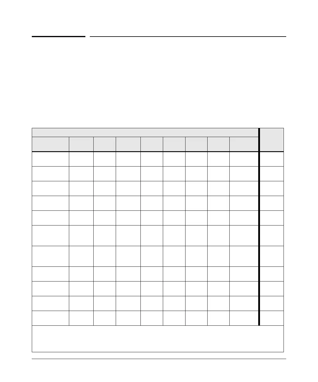
■ Table 5-1 shows LED patterns on the switch that indicate switch problem
conditions.
■ Table 5-2 shows LED patterns on the switches and on stacking modules
in a stack that indicate stack-related problem conditions.
1. Check in the tables for the LED pattern you see on your switch and
stacking module.
2. Refer to the corresponding diagnostic tip on the next few pages.
Table 5-1. Switch LED Error Indicators
LED Pattern Indicating Problems
See
Diag Tips
Power Fault Tmp Test PoE Fan PS Mdl **
Port
Link LED
off with power
cord plugged in
******* *
1
on
prolonged
on
*
prolonged
on
**** *
2
on
blink
orange
†
*
blink
orange
†
**** *
3
on
blink
orange
†
*off*
blink
orange
†
** *
4
on
blink
orange
†
*
blink
orange
†
* * * * blink orange
†
5
on off * off * * * *
off with
cable
connected
6
on off * off * * * *
on, but no
activity on
the port
7
on
blink
orange
†
****
blink
orange
†
**
8
on
blink
orange
†
blink
orange
†
***** *
9
on
blink
orange
†
**
blink
orange
†
** *
10
on
blink
orange
†
****
*
blink
orange
†
*
11
* This LED is not important for the diagnosis.
†
The blinking behavior is an on/off cycle once every 1.6 seconds, approximately.
** The Mdl LED is on the switch front. It is replicated by the Mdl Status LED on the 10G Expansion Modules.
Note that this LED is also used to report the status of a Stacking Module installed in the switch. See Table 5-2.