2-11
Installing the Switch
Installation Procedures
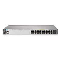
Figure 2-8. Location of Module Status LEDs
If the module is installed properly and the switch is powered on, the module
undergoes a self test that takes a few seconds. You can use the LEDs to
determine that the module is installed properly and has passed the self test,
as described in the “LED Behavior” table below.
Table 2-2. Stacking Module LED Behavior
LED Display for a Properly Installed Module
Mdl LED on the front
of the switch and
Module Status LED
on the module
The LED goes ON as soon as the module is installed and the switch
is powered on, and stays ON steadily.
Fault OFF normal state, no fault condition exist.
Link (for each
stacking port on the
module)
If stacking cables are connected to the module and to a Stacking
Module on another powered on HP 2920 switch, the LED goes ON
to indicate the stacking port is enabled, connected, and detects a
signal from the attached switch.
Module (Mdl) Status
LED
Fault LED