2-30
Installing the Switch
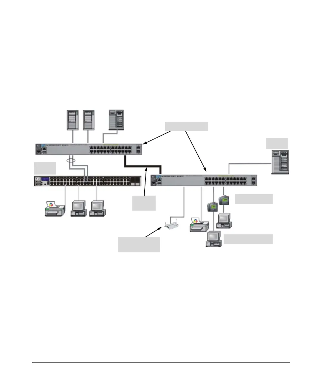
Sample Network Topologies
Category 3 or 4 cable can also be used if the connection is 10 Mbps only. In all
cases, the device ports must be configured to auto negotiate the link
characteristics for this feature to work.
The switch, in turn, can be connected to a network backbone through fiber-
optic cabling connected to a Gigabit-SX, -LX, or -LH transceiver installed in
the switch. Now, all the devices on these network segments can access other
network resources that are connected elsewhere on the network backbone.
Figure 2-26. Example as a Segment Switch Implementing PoE/PoE+
As shown in Figure 2-28, the IP telephones have been inserted in between the
HP 2920-PoE+ switch and the PCs, and a WAP has been connected to the HP
2920-PoE+ switch. Only devices directly connected to the PoE+ switches can
receive PoE/PoE+ power. Devices connected to a non-PoE+ switch cannot
receive PoE/PoE+ power.
Server
PCs and peripherals
IP Telephones
Stacking
cables
Wireless Access
Point
Non-PoE
Switch
HP 2920-24G Switch