2-14 Removal and Replacement HP Omnibook 6000/6100
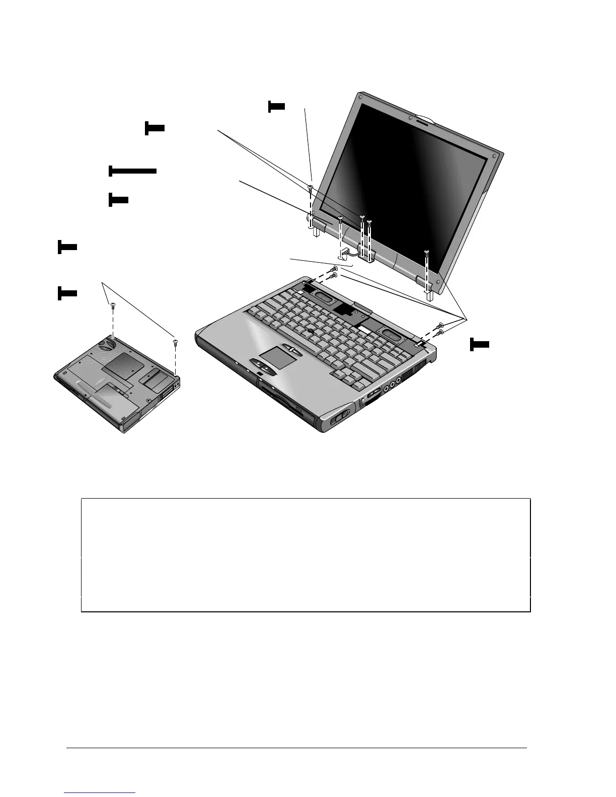
Figure 2-10. Removing the Display
Reassembly Notes
• Before installing any screws, make sure the center hinge cover fits over the tab in the bottom case.
Important
• Make sure the DIP switches on the display interface PCA match the settings shown on the
label on the display cable, or you risk damaging the display.
• Omnibook 6100: Reprogram the BIOS IC, preferably with the latest BIOS for display
compatibility.
• Omnibook 6000: If you change the DIP switches, use the service utilities disk to reprogram
the EEPROM—see page 2-31. If the EEPROM is not programmed correctly, the display will
not turn on.
Screws,
M2.5×6mm (5)
Screws, M2.5×8mm (2)
(OB 6100)
Screws, M2.5×6mm (2)
(OB 6000)
Screws, M2.5×4 mm
(1 on OB 6100 models,
2 on some OB 6000 models)
Label with DIP
switch settings
Screw, M2.5×17mm (OB 6100)
Screw, M2.5 x 6mm (OB 6000)
Screw, M2.5×5mm