5
Cooling
Plan the installation site for adequate ventilation.
• Leave at least 10 cm (3.94 in) of clearance at the inlet and outlet air vents.
• The rack for the switch has a good cooling system.
• The installation site has a good cooling system.
• Verify that the airflow design of the chassis meets the airflow design of the installation site.
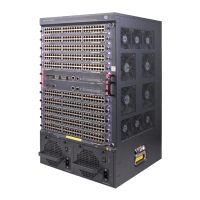
Figure 1 Airflow through the 7506-V chassis
(1) Inlet air vents for the power supplies
(2) Outlet air vents for the power supplies
(3) Inlet air vents for the chassis (4) Outlet air vents for the chassis
1
1
2
3
3
4
4
4

 Loading...