6
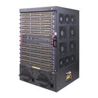
Figure 2 Airflow through other 7500 switch chassis
(1) Inlet air vents for the power supplies (2) Outlet air vents for the power supplies
(3) Inlet air vents for the chassis (4) Outlet air vents for the chassis
Space
For easy maintenance, follow these guidelines:
• Reserve at least 1 m (3.28 ft) of clearance between the rack and walls or other devices.
• The equipment room is at least 3 m (9.84 ft) high.
Installation tools
Table 6 lists the tools and equipment that you might need during installation. All of them are user
supplied.
Table 6 Installation tools and equipment
Cate
Tool
Measuring and
marking tools
Long tape, ruler (of 1 meter), gradienter, marker, chalk line, and pencil
Drills Percussion drill, electric drill, and several auxiliary drill bits
Fastening tools
Flat-blade screwdriver P4-75 mm
Phillips screwdriver P1-100 mm, P2-150 mm, and P3-250 mm
Socket wrench M5
Socket wrench M6
Small tools
Needle-nose pliers, diagonal pliers, combination pliers, wire-stripping pliers, crimping
pliers, RJ-45 crimping pliers, file, and handsaw
Auxiliary tools
ESD wrist strap, hair brush, tweezers, paper knife, hand bellows, electric iron, solder
wire, ladder, cable stripper, vacuum cleaner, crowbar, and rubber hammer

 Loading...