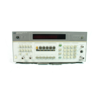
Operation Model 8901B
NOTE
The following tables are intended
as
a reference for advanced users who
are
familiar with the
HP
8901B
measurement capabilities.
Table 3-1 3, “Measurement Modes and Codes”.
All
of the functions listed on this table are defined
as “measurement modes” in the instrument. The instrument can only be in one Measurement Mode at
a time.
If
a measurement mode
is
volatile, pushing the CLEAR key
or
entering CL over the bus,
will
return the instrument
to
the last selected, non-volatile measurement mode.
This table lists all the measurement modes of the HP 8901B Modulation Analyzer and their
programming codes. This table also lists whether
or
not the measurement mode
is
volatile, whether the
receiver section of the HP 8901B is used to make the measurement, and whether the Demodulation
Output is blanked during the measurement.
Table 3-1
4,
“Measurement Modifiers”.
Whenever
a
measurement
is
selected, the Modulation
Analyzer sets up
its
internal circuitry
so
it
can make the most accurate measurement possible. These
settings can be altered by the operator
to
modify the measurement.
This table lists the measurement modifiers for the primary measurement modes listed
in
Table 3-13,
“Measurement Modes and Codes”.
To see what modifiers are being automatically selected,
e
use the Special Special display
to
read the Range
in
use,
0
read the front-panel lights for the Detectors,
Filters
and De-Emphasis
in
use and
0
see Table 3-15
or
-16, “EnablingDisabling Variable Parameters (Front Panel
or
Remote)” for
a summary of how
to
read the Calibration Factors, the Frequency Offset, the
dB
external
Attenuation, the Limits set, and whether Ratio has been selected.
Table 3-1
5,
“Enabling/Disabling Variable Parameters (Front Panel)”.
This table lists ways of
verifying from the front panel the values of the Calibration Factors, Frequency Offset,
dB
External
Attenuator, Limitwtio and Set Reference functions.
Table 3-1
6,
“Enabling/Disabling Variable Parameters (Remote)”.
This table
is
the same
as
Table
3-15 except that
it
shows the programming codes required instead of the front-panel keystrokes.
Table 3-17, “HP 8901A/02A Code Differences”.
This table lists the function code differences for
identical functions of the HP 8901B and the HP 8901A, and should be useful in modifying existing
HP 8901A control programs
to
drive an HP 8901B.
3-8.
DATA
OUTPUT
Data Output Format
Numeric Data.
As shown below, the output data
is
always in the form of an implicit-point exponential
constant. Data is always output in fundamental units (for example, Hz, watts, radians,
dB,
%,
etc.),
and the decimal point (not sent)
is
assumed to be
to
the right of the tenth digit of the mantissa.
Data values never exceed +9
000
000
OOOE-tOl. Output values greater than this are Error Messages.
Output data is displayed using the following format:
first
the sign, then
10
digits (leading zeros not
suppressed) followed by the letter
E
and a signed two-digit exponent. The last
two
characters of the
string are a carriage return (CR) and a line feed
(LF)
in string positions 16 and
17.
Refer
to
Table 3-5,
“Data Output Examples” for examples.
3-18

 Loading...