Model
8901B
Operation
Selective Power Measurements (Option
030)
FUNCTIONS
Special Functions
23
(External
LO)
and
24
(Selective Power Measurements)
DESCRIPTION
The Series
030,
Selective Power Measurement Options enable the Modulation Analyzer to measure
adjacent-channel power and single-sideband noise on continuous wave
(CW)
RF signals. Both
measurements basically consist of tuning the instrument to the RF signal, measuring the
IF
level
in the passband of a selected
IF
filter, then offsetting the signal onto the skirt of the
IF
filter and
re-measuring the
IF
level. Offsetting the signal places a portion of the sideband noise of the carrier in
the passband of the
IF
filter. The ratio of the out-of-band
IF
level to the in-band
IF
level
is
the desired
measurement result (expressed in
dB).
The measurement procedure requires that the operator step through a sequence of special functions
and increment either the local oscillator
(LO)
or
the signal source. For RF signal frequencies above
300
MHz, an external
LO
is
recommended for greatest sensitivity and accuracy. Special Function
23
switches the
LO
between internal and external. The external
LO
connects to a rear-panel connector.
(Since Option Series
030
provide rear-panel
LO
input and output connectors, Option
003
is not available
in conjunction with the
030
Series Options.)
The
030
Series Options include the choice of
two
IF
bandpass filters installed. The bandwidths of these
IF
filters match the requirements of specific industry
standards
for measuring adjacent-channel power.
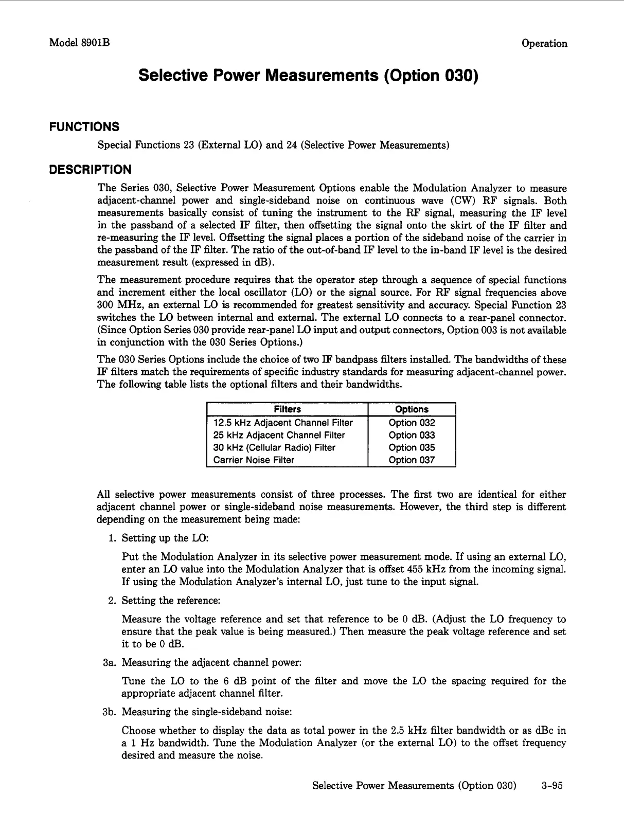
The following table lists the optional filters and their bandwidths.
I
Filters
I
ODtions
I
12.5
kHz
Adjacent Channel Filter
25
kHz
Adjacent Channel
Filter
30
kHz
(Cellular Radio)
Filter
Option
032
Option
033
Option
035
I
Carrier Noise
Filter
Option
037
All selective power measurements consist of three processes. The first
two
are identical for either
adjacent channel power
or
single-sideband noise measurements. However, the third step is different
depending on the measurement being made:
1.
Setting up the
LO:
Put the Modulation Analyzer in its selective power measurement mode.
If
using an external
LO,
enter an
LO
value into the Modulation Analyzer that
is
offset
455
kHz from the incoming signal.
If
using the Modulation Analyzer’s internal
LO,
just tune
to
the input signal.
2.
Setting the reference:
Measure the voltage reference and set that reference to be
0
dB.
(Adjust the
LO
frequency to
ensure that the peak value
is
being measured.) Then measure the peak voltage reference and set
it
to be
0
dl3.
3a. Measuring the adjacent channel power:
The the
LO
to the
6
dE3
point of the filter and move the
LO
the spacing required for the
appropriate adjacent channel filter.
3b.
Measuring the single-sideband noise:
Choose whether to display the data as total power in the
2.5
kHz filter bandwidth
or
as dBc in
a
1
Hz bandwidth. Tune the Modulation Analyzer
(or
the external
LO)
to the offset frequency
desired and measure the noise.
Selective Power Measurements (Option
030)
3-95

 Loading...


