Model
8901B
Operation
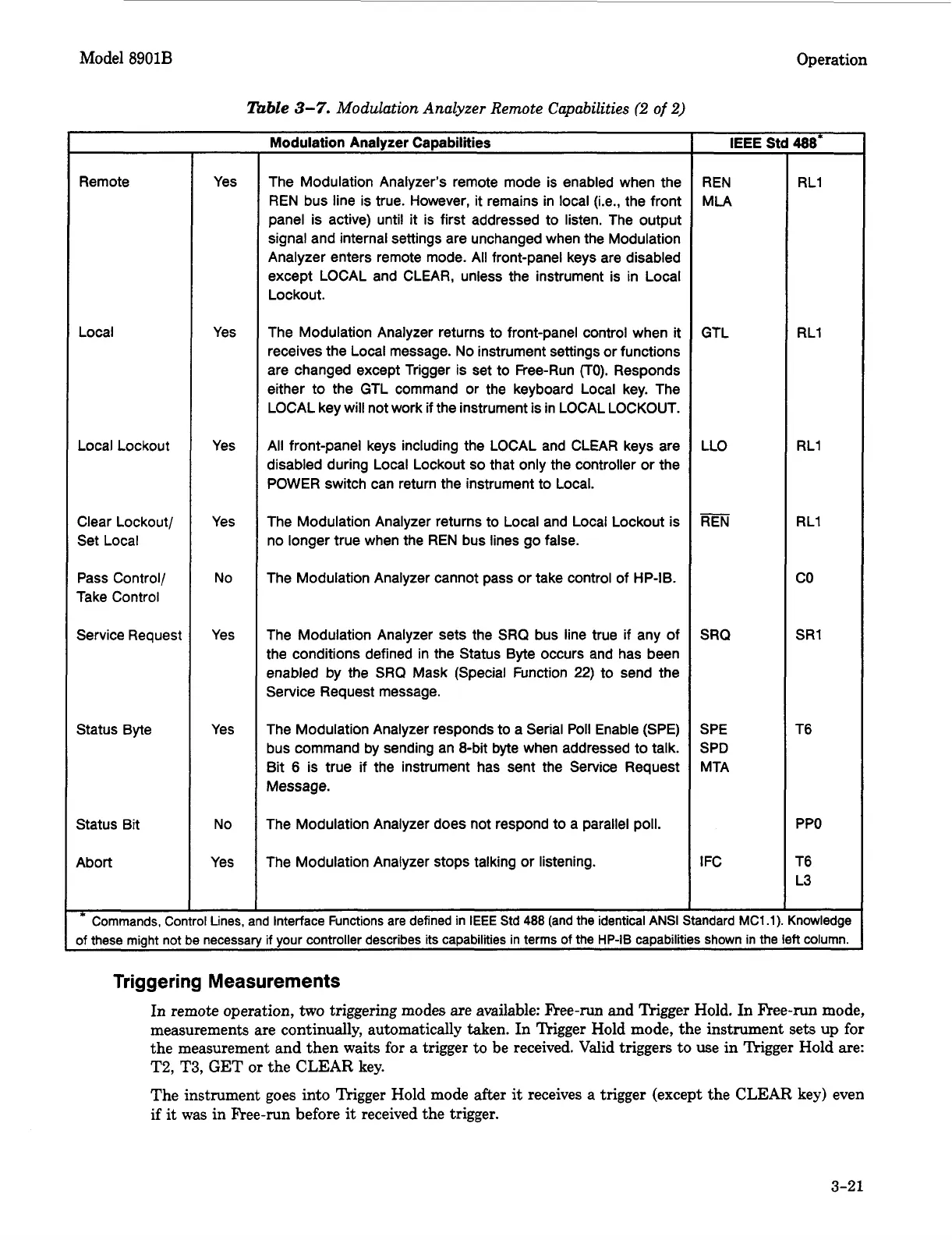
Table
3-7.
Modulation Analyzer Remote Capabilities
(2
of
2)
Remote
Local
Local Lockout
Clear Lockout/
Set Local
Pass Control/
Take Control
Service Request
Status Byte
Status Bit
Abort
Yes
Yes
Yes
Yes
No
Yes
Yes
No
Yes
Modulation Analyzer Capabilities
The Modulation Analyzer’s remote mode is enabled when the
REN bus line is true. However, it remains in local (i.e., the front
panel is active) until
it
is first addressed to listen. The output
signal and internal settings are unchanged when the Modulation
Analyzer enters remote mode.
All
front-panel keys are disabled
except LOCAL and CLEAR, unless the instrument is in Local
Lockout.
The Modulation Analyzer returns to front-panel control when
it
receives the Local message. No instrument settings or functions
are changed except Trigger is set to Free-Run
(TO).
Responds
either to the GTL command or the keyboard Local key. The
LOCAL key will not work
if
the instrument is in LOCAL LOCKOUT.
All front-panel keys including the LOCAL and CLEAR keys are
disabled during Local Lockout
so
that only the controller or the
POWER switch can return the instrument to Local.
The Modulation Analyzer returns to Local and Local Lockout is
no longer true when the REN bus lines go false.
The Modulation Analyzer cannot pass or take control of HP-IB.
The Modulation Analyzer sets the SRQ bus line true if any of
the conditions defined in the Status Byte occurs and has been
enabled by the
SRQ
Mask (Special Function
22)
to send the
Service Request message.
The Modulation Analyzer responds to a Serial Poll Enable (SPE)
bus command by sending an 8-bit byte when addressed to talk.
Bit 6 is true
if
the instrument has sent the Service Request
Message.
The Modulation Analyzer does not respond to a parallel poll.
The Modulation Analyzer stops talking or listening.
*
Commands, Control Lines, and Interface Functions are defined in
IEEE
Std
488
(and the identical
ANSI
IEEE
Std 488*
REN
MLA
GTL
LLO
REN
SRQ
SPE
SPD
MTA
I
FC
ndard MC1.11
RL1
RL1
RL1
RL1
co
SR1
T6
PPO
T6
L3
howledge
sf these might not be necessary if your controller describes its capabilities in terms of the
HP-IB
capabilities shown in the left column.
Triggering Measurements
In
remote operation, two triggering modes
are
available:
F’ree-run
and
Trigger
Hold.
In
Free-run
mode,
measurements are continually, automatically
taken.
In
Trigger Hold mode,
the
instrument
sets
up
for
the
measurement and
then
waits for a trigger to
be
received. Valid triggers to use
in
Trigger Hold
are:
T2,
T3,
GET
or
the
CLEAR
key.
The
instrument goes into Trigger Hold mode after
it
receives
a
trigger (except
the
CLEAR key)
even
if
it
was
in
Flee-run
before
it
received
the
trigger.
3-21

 Loading...


