Model
8901B
Operation
INPUT
ATTENUATOR IF AMP
-1
~~~~~
Do
not apply greater than
40
Vdc or greater than
+15
dBm into the
rear-panel IF
OUTPUT
connector.
ClRCU
IF
BUFFER
-
DESCRIPTION
The rear-panel
IF
OUTPUT (a female
BNC
connector) provides a buffered output to enable monitoring
of the Modulation Analyzer’s
IF
signal. The ac-coupled signal ranges from
150
kHz
to
2.5
MHz and
normally varies in level from
-27
to
-3
dBm (into
50
ohms). The level variation depends on the RF
input signal level, RF input attenuation setting, and the measurement selected.
The
3
dB
bandwidth of the signal at
IF
OUTPUT
is
approximately
3
MHz when the instrument uses
the wide,
2.5
MHz low-pass filter and approximately
200
kHz when the instrument uses the wide,
455
kHz
bandpass filter.
At any particular input level and front-panel setting, the flatness of the
IF
OUTPUT,
as
input frequency
varies, is typically within
k5%.
BLOCK DIAGRAM
TO
OTHER
-
MEASUREMENT
ITS
I-
L
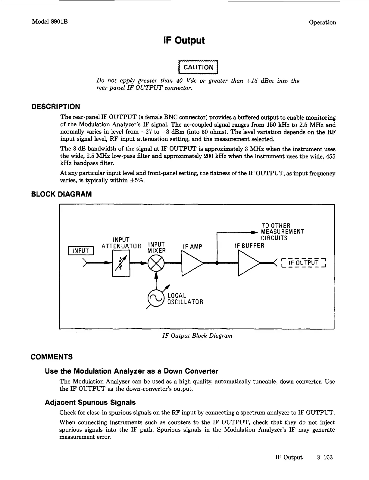
IF Output Block Diagram
COMMENTS
Use the Modulation Analyzer as a Down Converter
The Modulation Analyzer can be used as a high-quality, automatically tuneable, down-converter. Use
the
IF
OUTPUT
as
the down-converter’s output.
Adjacent Spurious Signals
Check for close-in spurious signals on the RF input by connecting a spectrum analyzer
to
IF
OUTPUT.
When connecting instruments
such
as counters to the
IF
OUTPUT, check that they do not inject
spurious signals into the
IF
path. Spurious signals in the Modulation Analyzer’s
IF
may generate
measurement error.
IF
Output
3-103