Model
8901B
Operation
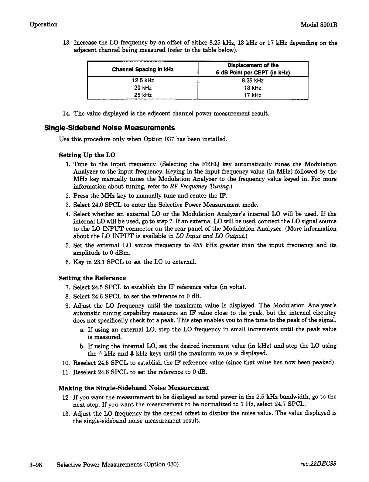
Channel Spacing in
kHz
12.5
kHz
20
kHz
25
kHz
13.
Increase the LO frequency by an offset of either
8.25
kHz,
13
kHz or
17
kHz depending on the
adjacent channel being measured (refer to the table below).
Displacement
of
the
6
dB
Point per CEPT (in
kHr)
8.25
kHz
13
kHz
17
kHz
14.
The value displayed is the adjacent channel power measurement result.
Single-Sideband Noise Measurements
Use this procedure only when Option
037
has been installed.
Setting
Up
the
LO
1.
2.
3.
4.
5.
6.
Tune to the input frequency. (Selecting the FREQ key automatically tunes the Modulation
Analyzer to the input frequency. Keying in the input frequency value (in MHz) followed by the
MHz key manually tunes the Modulation Analyzer to the frequency value keyed in. For more
information about tuning, refer to
RF
frequency
!lLning.)
Press the MHz key to manually tune and center the
IF.
Select
24.0
SPCL to enter the Selective Power Measurement mode.
Select whether an external LO or the Modulation Analyzer’s internal LO will be used. If the
internal LO will be used, go
to
step
7.
If
an
external LO will be used, connect the LO signal source
to the LO INPUT connector on the rear panel of the Modulation Analyzer. (More information
about the LO INPUT is available in
LO
Input
and
LO
Output.)
Set the external LO source frequency to
455
kHz greater than the input frequency and its
amplitude to
0
dBm.
Key in
23.1
SPCL to set the LO to external.
Setting the Reference
7.
Select
24.5
SPCL to establish the IF reference value (in volts).
8.
Select
24.6
SPCL to set the reference
to
0
dl3.
9.
Adjust the
LO
frequency until the maximum value is displayed. The Modulation Analyzer’s
automatic tuning capability measures an
IF
value close to the peak, but the internal circuitry
does not specifically check for a peak. This step enables you to fine tune to the peak of the signal.
a.
If
using an external LO, step the LO frequency in small increments until the peak value
b. If using the internal LO, set the desired increment value (in kHz) and step the LO using
10.
Reselect
24.5
SPCL to establish the IF reference value (since that value has now been peaked).
11.
Reselect
24.6
SPCL to set the reference to
0
dl3.
is measured.
the
0
kHz and
4
kHz keys until the maximum value is displayed.
Making the Single-Sideband Noise Measurement
12.
If
you want the measurement to be displayed as total power in the
2.5
kHz bandwidth, go to the
13.
Adjust the LO frequency by the desired offset to display the noise value. The value displayed is
next step. If you want the measurement to be normalized to
1
Hz,
select
24.7
SPCL.
the single-sideband noise measurement result.
3-98
Selective Power Measurements (Option
030)
rev.22DEC88

 Loading...


