Operation Model 8901B
WIOE
455kHZ
INPUT
EP
OR
2.5MHZ
ATTENUATION
,.,-.,.
LP
FILTER
AM
y$p~
OEMOOULATOR
7
VOLTMETER
7
run
1F
IYC
(OPTION
SERIE5
030
ONLY1
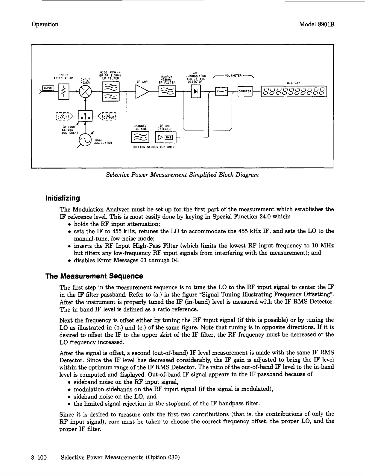
Selective Power Measurement Simplified
Block
Diagram
Initializing
The Modulation Analyzer must be set up for the
first
part of the measurement which establishes the
IF reference level. This is most easily done by keying in Special Function
24.0
which
0
holds the RF input attenuation;
0
sets the IF to
455
kHz,
retunes the
LO
to
accommodate the
455
kHz
IF, and sets the
LO
to the
manual-tune, low-noise mode;
0
inserts the RF Input High-Pass Filter (which limits the lowest RF input frequency to
10
MHz
but filters
any
low-frequency RF input
signals
from interfering with the measurement); and
0
disables
Error
Messages 01 through
04.
The Measurement Sequence
The first step in the measurement sequence
is
to
tune the
LO
to
the RF input signal
to
center the IF
in the IF filter passband. Refer to (a.) in the figure "Signal Tuning Illustrating Frequency Offsetting".
After the instrument
is
properly tuned the
IF
(in-band) level
is
measured with the
IF
RMS Detector.
The in-band IF level is defined
as
a
ratio reference.
Next the frequency is offset either by tuning the RF input signal
(if
this is possible)
or
by tuning the
LO
as
illustrated in (b.) and (c.) of the same figure. Note that tuning is in opposite directions. If
it
is
desired to offset the IF
to
the upper skirt of the
IF
filter, the RF frequency must be decreased
or
the
LO
frequency increased.
After the signal
is
offset, a second (out-of-band) IF level measurement is made with the same IF RMS
Detector. Since the IF level has decreased considerably, the IF gain
is
adjusted to bring the
IF
level
within the optimum range of the IF RMS Detector. The ratio of the out-of-band
IF
level to the in-band
level is computed and displayed. Out-of-band
IF
signal appears in the IF passband because of
0
sideband noise on the RF input signal,
0
modulation sidebands on the RF input signal
(if
the signal
is
modulated),
0
sideband noise
on
the
LO,
and
0
the limited signal rejection in the stopband of the
IF
bandpass filter.
Since it is desired to measure only the first
two
contributions (that is, the contributions of only the
RF input signal), care must be taken to choose the correct frequency offset, the proper
LO,
and the
proper IF filter.
3-100
Selective Power Measurements (Option 030)

 Loading...


