Operation Model 8901B
COUNTER/
fw
CONTROLLER
-
OSCl
L
LATO
R
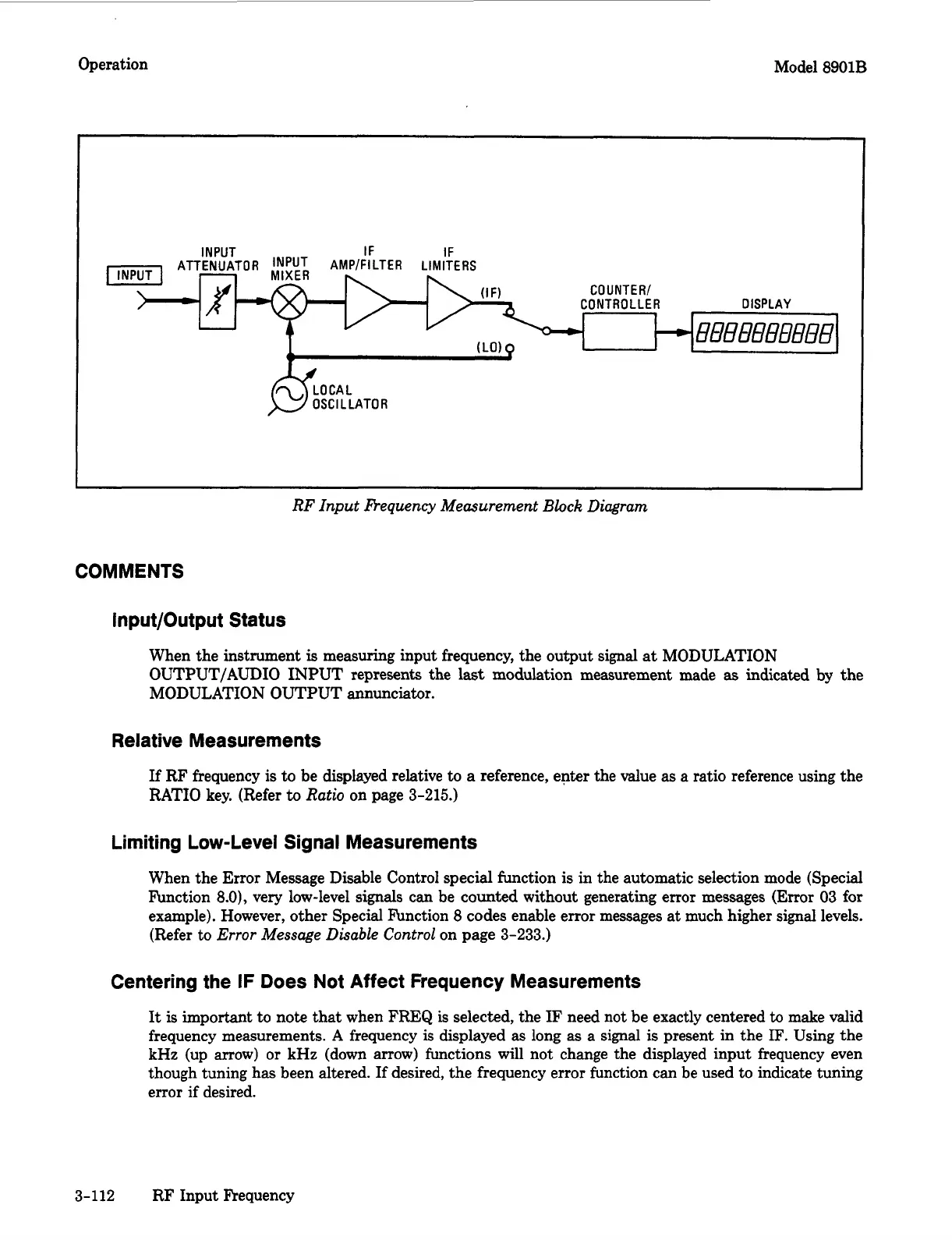
RF Input Bequency Measurement
Block
Diagram
COMMENTS
lnput/Output Status
When the instrument
is
measuring input frequency, the output signal
at
MODULATION
OUTPUT/AUDIO INPUT represents the
last
modulation measurement made
as
indicated by the
MODULATION OUTPUT annunciator.
Relative Measurements
If
RF frequency is to be displayed relative to
a
reference, enter the value
as
a ratio reference using the
RATIO
key. (Refer
to
Ratio
on page
3-215.)
Limiting Low-Level Signal Measurements
When the
Error
Message Disable Control special function is in the automatic selection mode (Special
Function
8.0),
very low-level
signals
can be counted without generating error messages
(Error
03 for
example). However, other Special F’unction
8
codes enable error messages at much higher signal levels.
(Refer
to
Error
Message Disable Control
on page
3-233.)
Centering the IF Does Not Affect Frequency Measurements
It
is
important
to note that when
FREQ
is selected, the
IF
need not be exactly centered
to
make valid
frequency measurements.
A
frequency is displayed as long as a signal
is
present in the
IF.
Using the
kHz
(up
arrow)
or
kHz
(down arrow) functions will not change the displayed input frequency even
though tuning has been altered. If desired, the frequency error function can be used to indicate tuning
error if desired.
3-112 RF Input Frequency

 Loading...


