Operation Model
8901B
HP-I8
PROGRAM CODES
FREQ ERROR
=
S5
MHz
=
MZ
MEASUREMENT TECHNIQUE
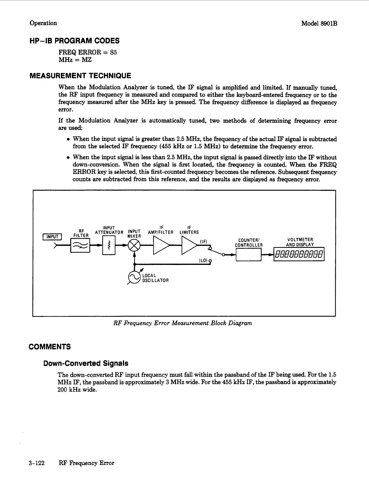
When the Modulation Analyzer
is
tuned, the
IF
signal
is
amplified and limited.
If
manually
tuned,
the RF input frequency
is
measured and compared
to
either the keyboard-entered frequency or
to
the
frequency measured after the MHz key
is
pressed. The frequency difference
is
displayed
as
frequency
error.
If
the Modulation Analyzer
is
automatically tuned,
two
methods of determining frequency error
are used
0
When the input signal
is
greater than
2.5
MHz, the frequency of the actual
IF
signal
is
subtracted
from the selected
IF
frequency
(455
kHz or
1.5
MHz)
to
determine the frequency error.
0
When the input signal
is
less than
2.5
MHz, the input
signal
is
passed directly into the
IF
without
down-conversion. When the signal
is
first
located, the frequency
is
counted. When the FREQ
ERROR key is selected, this first-counted frequency becomes the reference. Subsequent frequency
counts are subtracted from this reference, and the results are displayed
as
frequency error.
I
CO UNTE
RI
VOLTMETER
CONTROLLER AND DISPLAY
,
c
(LO)
p
I
;
08081
-
OSCILLATOR
~ ~~~~~~
RF
Requency
Error
Measurement
Block
Diagram
COMMENTS
Down-Converted Signals
The down-converted RF input frequency must fall within the passband of the
IF
being used. For the
1.5
MHz IF, the passband
is
approximately
3
MHz wide. For the
455
kHz IF, the passband
is
approximately
200
kHz wide.
3-122
RF Frequency Error
 Loading...


