Model 8901B Operation
LO
Input and
LO
Output (Option
003)
Do
not apply greater than
40
Vdc
or
+5
dBm
of
RF
power into the
u)
INPUT
or
damage to the instrument may result. Do not apply dc voltage
or
RFpower
into
the
LO
OUTPUT
or
damage
to
the instrument
may
result.
DESCRIPTION
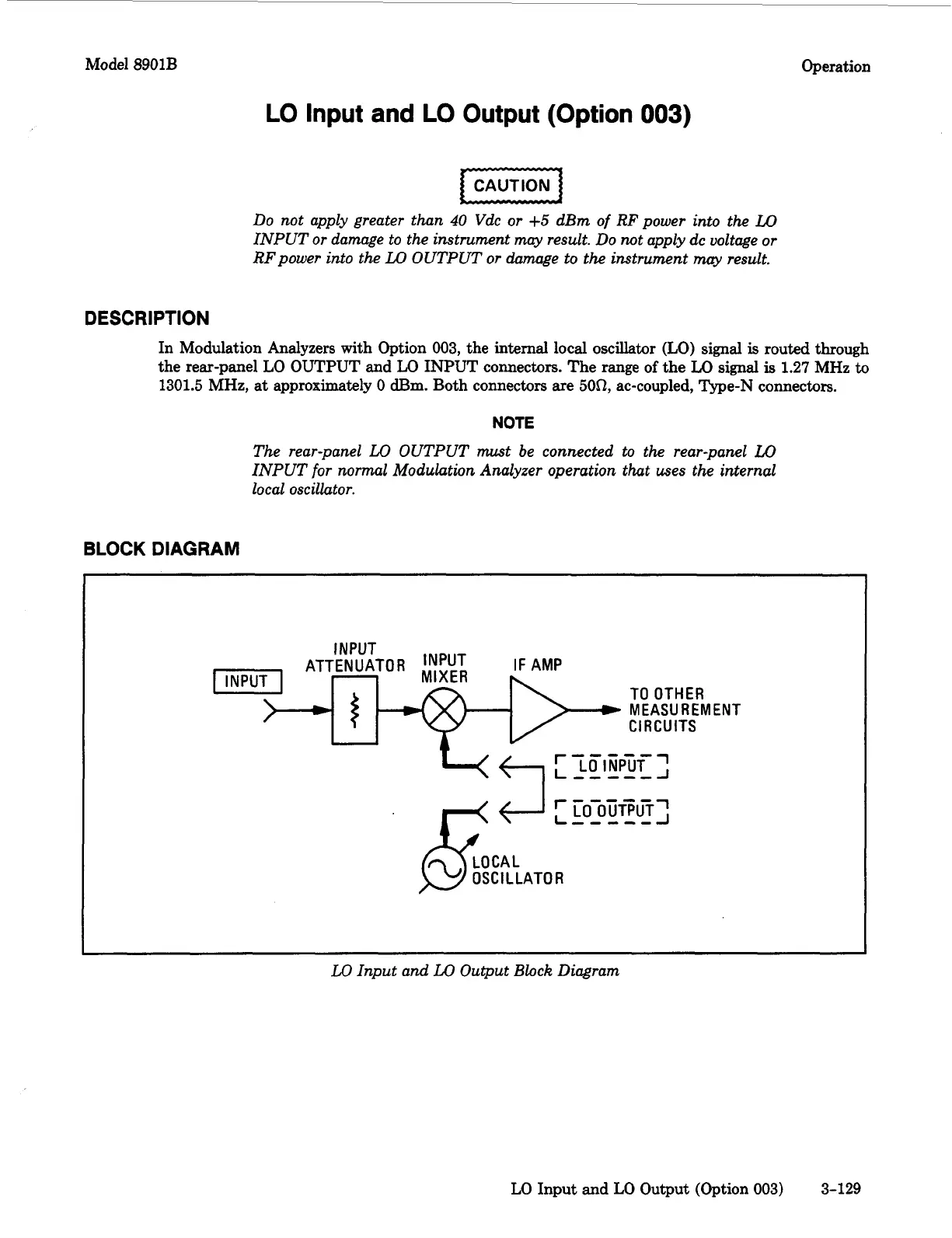
In Modulation Analyzers with Option 003, the internal local oscillator
(LO)
signal
is
routed through
the rear-panel
LO
OUTPUT and
LO
INPUT connectors. The range
of
the
LO
signal
is
1.27 MHz
to
1301.5 MHz, at approximately
0
am.
Both connectors are 500, ac-coupled, Type-N connectors.
NOTE
The rear-panel
u)
OUTPUT
must
be connected to the rear-panel
u)
INPUT
for
normal Modulation Analyzer operation that wes the internal
local oscillator.
BLOCK DIAGRAM
ATTENUATOR
INPUT
INPUT
IF
AMP
TO
OTHER
MEASUREMENT
CI
RCU ITS
LO
Input and
u)
Output
Block
Diagram
LO
Input
and
LO
Output (Option 003)
3-129

 Loading...


