Operation Model 8901B
BLOCK
DIAGRAM
MODULATION OUTPUT/
AUDIO INPUT
I
CfllINJER
.
-
-
..
.
-
.
.
AN0 DISPLAY
I
LOCAL
OSCILLATOR
DETECTOR
DISTORTION AUOlO
RMS
AUOIO
COUNTER
n
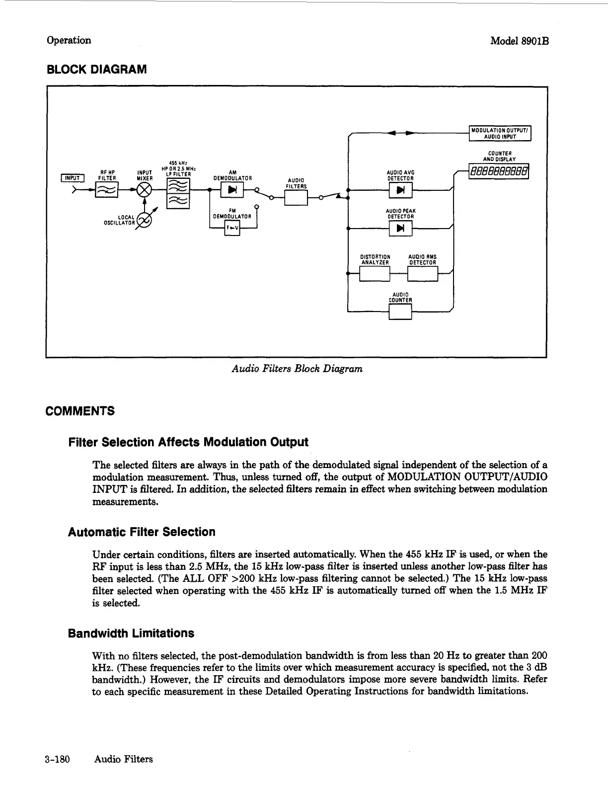
Audio
Filters
Block
Diagram
COMMENTS
Filter Selection Affects Modulation Output
The selected filters are always in the path of the demodulated signal independent of the selection of
a
modulation measurement. Thus, unless turned
off,
the output of MODULATION OUTPUT/AUDIO
INPUT is filtered. In addition, the selected
filters
remain in effect when switching between modulation
measurements.
Automatic Filter Selection
Under certain conditions, filters are inserted automatically. When the 455 kHz
IF
is
used, or when the
RF input
is
less than 2.5 MHz, the 15 kHz low-pass filter
is
inserted unless another low-pass filter
has
been selected. (The ALL OFF
>200
kHz
low-pass filtering cannot be selected.) The
15
kHz
low-pass
filter selected when operating with the 455 kHz
IF
is
automatically turned
off
when the 1.5 MHz
IF
is
selected.
Bandwidth Limitations
With no filters selected, the post-demodulation bandwidth
is
from less than
20
Hz
to
greater than
200
kHz. (These frequencies refer
to
the limits over which measurement accuracy
is
specified, not the
3
dB
bandwidth.) However, the
IF
circuits and demodulators impose more severe bandwidth limits. Refer
to each specific measurement in these Detailed Operating Instructions for bandwidth limitations.
3-180
Audio Filters

 Loading...


