Model
8901B
COMMENTS
~~
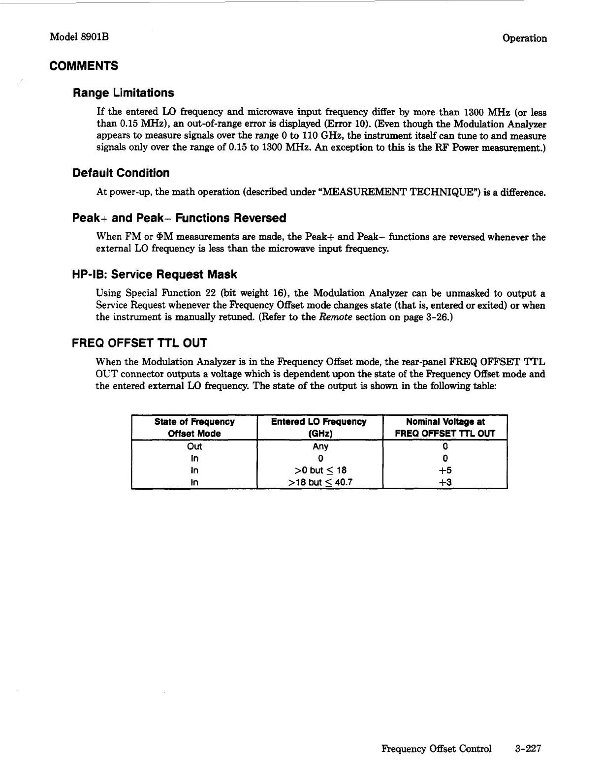
State
of
Frequency
Offset
Mode
out
In
In
In
Operation
Entered
LO
Frequency
Nominal
Voltage
at
(GHz) FREQ OFFSET
HL
OUT
Any
0
0
0
>O
but
5
18
+5
>18
but
<_
40.7
+3
Range Limitations
If
the entered
LO
frequency and microwave input frequency differ
by
more than
1300
MHz
(or
less
than
0.15
MHz),
an out-of-range error
is
displayed (Error
10).
(Even though the Modulation Analyzer
appears
to
measure
signals
over the range
0
to
110
GHz,
the instrument itself can tune
to
and measure
signals only over the range of
0.15
to
1300
MHz.
An exception
to
this
is
the
RF
Power measurement.)
Default Condition
At power-up, the math operation (described under “MEASUREMENT TECHNIQUE”)
is
a difference.
Peak+ and Peak- Functions Reversed
When
FM or bM
measurements are made, the Peak+ and Peak- functions are reversed whenever the
external
LO
frequency
is
less than the microwave input frequency.
HP-IB: Service Request Mask
Using
Special hnction
22
(bit weight
16),
the Modulation Analyzer can be unmasked
to
output
a
Service Request whenever the Fkequency Offset mode changes
state
(that
is,
entered or exited) or when
the instrument
is
manually retuned. (Refer
to
the
Remote
section on page
3-26.)
FREQ
OFFSET
TTL
OUT
When the Modulation Analyzer
is
in the Frequency Offset mode, the rear-panel FREQ
OFFSET
TTL
OUT
connector outputs a voltage which
is
dependent upon the
state
of the Frequency Offset mode
and
the entered external
LO
frequency. The
state
of
the output
is
shown in the following table:
Frequency Offset Control
3-227

 Loading...


