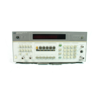
Model
8901B
General
Information
Table
1-1.
Specifications
(1
of
6)
ZERO DRIFT OF SENSORS
(1
HOUR,
AT CONSTANT
20.1%
offull scale of lowest range
for
11722A Sensor
TEMPERATURE AFTER 24-HOUR WARM-UP):
RF
Power
The HP 8901B Modulation Analyzer, with HP 11722A
Sensor Module, performs RF Power Measurements from
-20 dBm
(10
pW)
to
+30 dBm (1W) at frequencies from
100
kHz to
2.6
GHz. The 8901B can be used with any of
the HP 8480 series power sensors (8481A/lB/lH/2A/
2B/2H/3A/4A/5A) to make power measurements from
-70 dBm
(10
pW) to +44 dBm (25W) at frequencies from
100
kHz
to 26.5 GHz. The 8480 series sensors also work
with the HP 435A and HP 436A Power Meters. Unless
otherwise specified, the specifications shown below refer
to the 8901B only. A detailed explanation of how the un-
certainty specifications provided below affect the abso-
lute power measurement accuracy of the
8901B
is pro-
vided in Application Note
64-1.
RF POWER RESOLUTION':
Module and
848
IA/lB/l H/ZA/ZB/ZH/3A/SA
sensors.
22.0%
of full scale
of
lowest range
for
8484A sensor.
Decrease
by
a
factor
of
10
for
each higher range.
RF
'OWE'
RANGES
OF
8901B
MoDULATzoN
ANALYZER WITH
11
7224 SENSOR MODULE:
-20
dBm to
-10
dBm
(10
pW
to
100
pW),
range
1.
-10
dBm to
+O
dBm
(100
pW
to
1
mW),
range
2.
$0
dBm
to
+10
dBm
(1
mW
to
10
mW), range
3.
+IO
dBm to
$20
dBm
(10
mW
to
100
mW), range
4.
f20
dBm
to
$30
dBm
(100
mW to
lW),
range
5.
<IO
seconds, range
1.
<I
second, range
2.
<100
milliseconds, ranges
3-5.
DISPLAYED UNITS:
watts, dBm,
dBreiotive,
%re
,,,,,
dB
mV,
dB
pV.
RESPONSE TIME
(0
to
99%
OF READING):
0.1%
of full scale in watts
or
volts mode.
0.01
dB in dBm
or
dBTelative mode.
LINEARITY
(includes sensor non-linearity):
RF range linearity
2
RF range-to-range change error.
20.02 dB, RF ranges 2-5.
20.03 dB, RF range
1.
Using front-panel display add
21
count of
least-significant digit.
20.02 dB/RF Range Change from reference range.
volts,
mV,
pV,
dB
V.
RF RANGE LINEARITY
(using Recorder Outputfi
INTERNAL NON-VOLATILE CAL-FACTOR TABLES
(user-modifiable using special functions):
MAXIMUM NUMBER OF CAL
FACTORIFREQUENCY ENTRIES:
Table
#1
(Primary):
16
pairs plus Reference
CaI
Factor.
Table #2 (Frequency Offset):
22
pairs plus
Reference
CaJ
Factor.
MAXIMUM ALLOWED FREQUENCY ENTRY:
FREQUENCY ENTRY RESOLUTION:
50
kHz.
CAL FACTOR RANGE:
40
to
120%.
RF RANGE-TO-RANGE CHANGE ERROR:
INPUT SWR:
c1.15, using 11722A Sensor Module.
ZERO SET (DIGITAL SETTABILITP
OF
ZERO):
50.07% of full scale of lowest range.
Decrease by a factor of
10
for each higher range.
200
GHz.
Supplemental Characteristics:
__
CAL FACTOR RESOLUTION:
0.1
%.
ZERO
DRIFT OF METER:
20.03%
of
full scale/"C of lowest range.
Power
Reference
NOISE (at constant temperature, peak change over
any one-minute interval for the
11
722A Sensor
Module and
8481AIlBIlH/2A/2B/2H/3A/SA
Sensors):
0.4%
of full scale
on
range
1
(lowest range).
0.13%
of
full scale
on
range
2.
0.013%
of
full scale
on
range
3.
0.0013%
of
full
scale
on
range
4.
POWER
OUTPUT:
1.00
mW.
Factory set to
20.7%
traceable to the
U.S.
National Bureau of Standards.
year
[OOC
to
55OC).
ACCURACY:
21.2% worst case (20.9%
rss)
for one
0.00013%
ojfull scale
on
range
5.
For HP 8484A Sensor multiply noise
by
five
on
all
~ ~~ ~~~
Supplemental Characteristics:
FREQUENCY:
50
iMHz
nominal.
ranges.
The
8901B
fundamental RF Power measurement units are watts. Further
internal processing is done
on
this number
to
displa!, all other units.
When using
8484A
sensor the noise specification may mask the linearity
specification and became the predominont error. \\'hen operating
on
the
top AF power range. add the Power Sensor Linearity percentages
found
in
the power sensor specifications.
SWR:
1.05
nominal.
FRONT PANEL CONNECTOR:
Type-i\l
female.
All parameters describe performance in automatic operation or properly set manual conditions. Specifications de-
scribe the instrument's warranted performance. Supplemental Characteristics (shown in italics) are intended to pro-
vide information useful in applying the instrument by giving typical, but non-warranted, performance parameters.
1-19

 Loading...