Installation Model
8901B
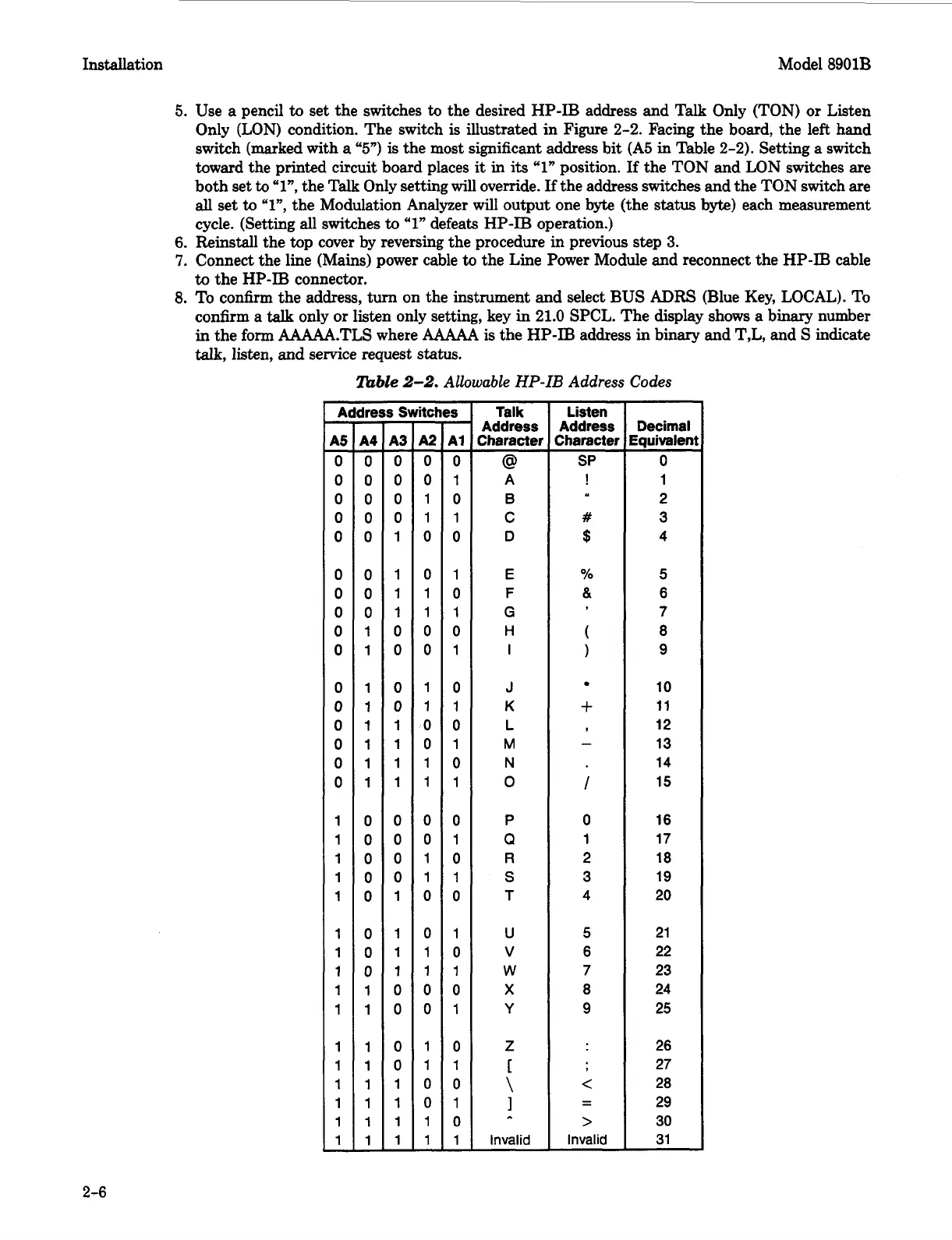
5.
Use
a
pencil
to
set the switches
to
the desired HP-IB address and Talk Only (TON) or Listen
Only (LON) condition. The switch
is
illustrated in Figure
2-2.
Facing the board, the left hand
switch (marked with
a
“5”)
is
the most significant address bit
(A5
in Table
2-2).
Setting a switch
toward the printed circuit board places
it
in
its
“1”
position. If the TON and LON switches are
both set
to
“l”,
the Talk Only setting will override.
If
the address switches and the TON switch are
all
set
to
“l”,
the Modulation Analyzer will output one byte (the
status
byte)
each measurement
cycle. (Setting
all
switches
to
“1”
defeats HP-IB operation.)
6.
Reinstall the
top
cover by reversing the procedure in previous step
3.
7.
Connect the line (Mains) power cable
to
the Line Power Module and reconnect the HP-IB cable
to
the HP-IB connector.
8.
To confirm the address,
turn
on the instrument and select BUS
ADRS
(Blue Key, LOCAL). To
confirm a
talk
only or listen only setting, key
in
21.0
SPCL. The display shows
a
binary number
in
the form AAAAA.TLS where
AAAM
is
the HP-IB address
in
binary and T,L, and
S
indicate
talk, listen, and service request
status.
lbble
2-2.
Allowable
HP-IB
Address Codes
A
95
0
0
0
0
0
0
0
0
0
0
0
0
0
0
0
0
1
1
1
1
1
1
1
1
1
1
1
1
1
1
1
1
-
-
-
ire
94
0
0
0
0
0
0
0
0
1
1
1
1
1
1
1
1
0
0
0
0
0
0
0
0
1
1
1
1
1
1
1
1
-
-
-
8s
43
0
0
0
0
1
1
1
1
0
0
0
0
1
1
1
1
0
0
0
0
1
1
1
1
0
0
0
0
1
1
1
1
-
-
-
itcl
A2
0
0
1
1
0
0
1
1
0
0
1
1
0
0
1
1
0
0
1
1
0
0
1
1
0
0
1
1
0
0
1
1
-
-
-
‘S
A1
0
1
0
1
0
1
0
1
0
1
0
1
0
1
0
1
0
1
0
1
0
1
0
1
0
1
0
1
0
1
0
1
-
-
-
Talk
Address
Character
A
B
C
D
E
F
G
H
i
J
K
L
M
N
0
P
Q
R
S
T
U
v
W
X
Y
Z
@
r
\
1
..
Invalid
Listen
Address
Zharacter
SP
!
#
$
%
&
(
1
+
-
I
0
1
2
3
4
5
6
7
8
9
c
>
Invalid
- -
Decimal
Equivalen
0
1
2
3
4
5
6
7
8
9
10
11
12
13
14
15
16
17
18
19
20
21
22
23
24
25
26
27
28
29
30
31
2-6
 Loading...


