Item
Power consumption
Hot-swapping
For
a Combo interface, the default operating interface is the electrical interface.
For a Combo interface, you can use either the electrical Ethernet interface or the optical
Ethernet interface. You can use the
view to switch between the optical and electrical interfaces. For details about the
Use optical transceivers provided by
optical transceivers and thus displays alarms automatically.
swapping" a module refers to first using the
the module, and then manually pulling it out, or inserting the module into its slot without
powering off the device. For details about the
LEDs
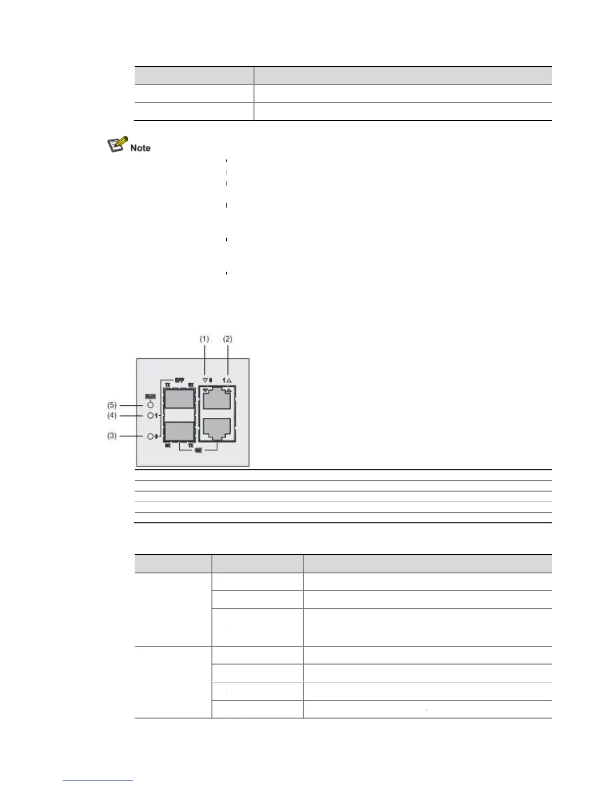
Figure 1-21 FIP-200 LEDs
(1) LED for 10/100/1000 Mbps electrical Ethernet interface 0 (GE0)
(2) LED for 10/100/1000 Mbps electrical Ethernet interface 1 (GE1)
(3) 1000 Mbps optical Ethernet interface LED (SFP0)
Ethernet interface LED (SFP1)
(5) Run LED (RUN)
Table 1-24
SFP0 and SFP1
(yellow/green)
a Combo interface, the default operating interface is the electrical interface.
For a Combo interface, you can use either the electrical Ethernet interface or the optical
Ethernet interface. You can use the
combo enable { copper | fiber
view to switch between the optical and electrical interfaces. For details about the
Ethernet Interfaces in the
Use optical transceivers provided by
only. The device may be incompatible with other
optical transceivers and thus displays alarms automatically.
swapping" a module refers to first using the
the module, and then manually pulling it out, or inserting the module into its slot without
powering off the device. For details about the
of HP SR6600 Routers User Manual.
(1) LED for 10/100/1000 Mbps electrical Ethernet interface 0 (GE0)
(2) LED for 10/100/1000 Mbps electrical Ethernet interface 1 (GE1)
(3) 1000 Mbps optical Ethernet interface LED (SFP0)
Ethernet interface LED (SFP1)
No power input is available or the FIP
Application program is being loaded (in this case, never power
No optical link is present.
An optical link is present.
Data is being sent or received at a rate of 1000 Mbps.
The optical transceiver has failed in POST.
a Combo interface, the default operating interface is the electrical interface.
For a Combo interface, you can use either the electrical Ethernet interface or the optical
view to switch between the optical and electrical interfaces. For details about the
only. The device may be incompatible with other
the module, and then manually pulling it out, or inserting the module into its slot without
No power input is available or the FIP
Application program is being loaded (in this case, never power
-200; otherwise, the FIP-200
Data is being sent or received at a rate of 1000 Mbps.
The optical transceiver has failed in POST.