LED Status Meaning
GE0 and GE1
(yellow/green)
Off No link is present.
Solid green A 1000 Mbps link is present.
Blinking green Data is being received or transmitted at a rate of 1000 Mbps.
Solid yellow A 10/100 Mbps link is present.
Blinking yellow Data is being received or transmitted at a rate of 10/100 Mbps.
Slots
FIP-200s can be inserted in Slot 0 through Slot 3 and Slot 6 through Slot 9 on the A6616. The
interface module slots on a FIP-200 are numbered 1 and 2 from right to left, as shown in Figure
1-22.
Figure 1-22 Interface module slots on the FIP-200
The numbers 1 and 2 in Figure 1-22 represent Slot 1 and Slot 2 respectively.
If only one MIM module is to be inserted into the FIP-200, it should be inserted into Slot 2
because only this slot has a connector.
Maximum interface modules provided by FIP-200s in full configuration
Table 1-25 Maximum interface modules provided by FIP-200s in full configuration
Interface module One RPE-X1 Two RPE-X1s One RSE-X1 Two RSE-X1s
FIP-200 8 8 Not supported Not supported
MIMs 16 16 — —
HIMs 16 16 — —
FIP-210
Introduction
The FIP-210 provides a high-speed service processing capability. The FIP-210 supports
SR6600 HIMs and MIMs. In consideration of smooth upgrade requirements, the FIP-210
supports two HIMs or two MIMs, or intermixing of a HIM and a MIM.
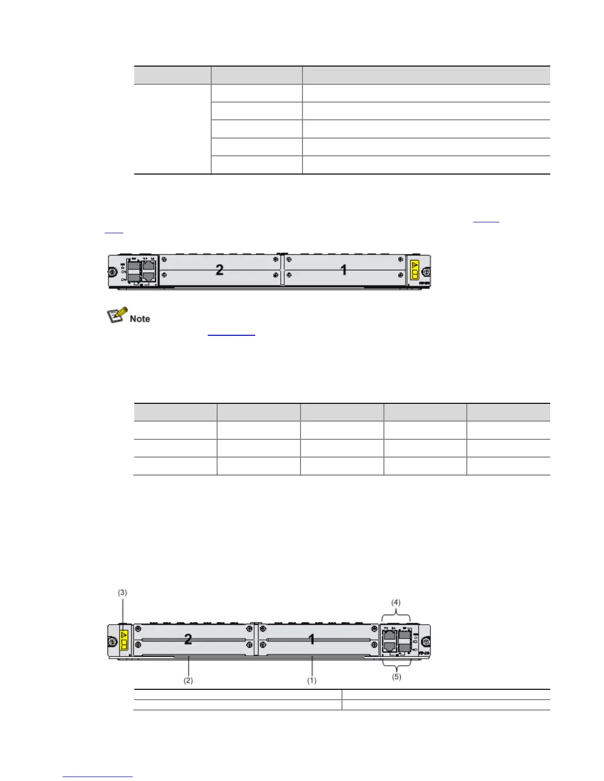
Figure 1-23 Front view of the FIP-210
(1) Slot 1 (2) Slot 2
(3) OPEN BOOK sign (4) Combo interface 1