39
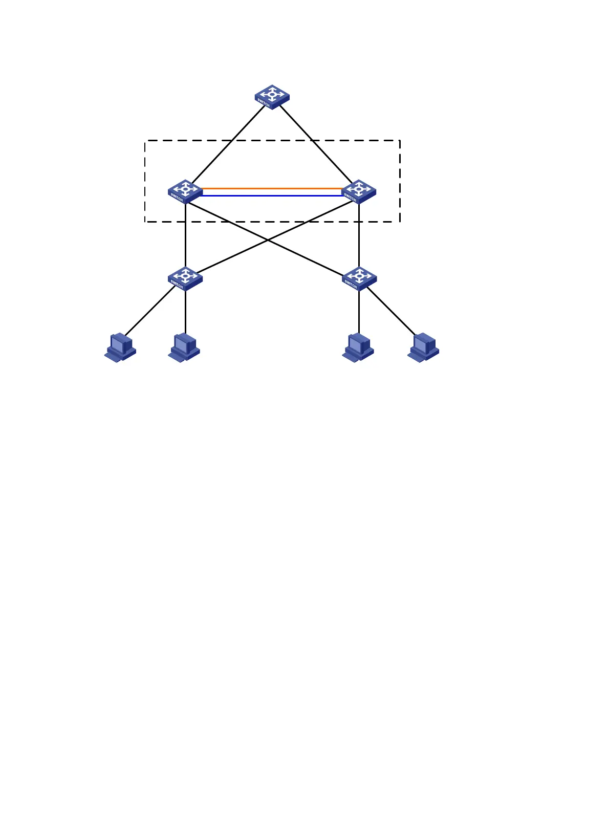
Figure 15 Network diagram
XGE1/3/0/1
(IRF-port1/2)
XGE2/3/0/1
(IRF-port2/1)
GE1/4/0/1
GE2/4/0/1
Device A
Device B
IRF
BFD MAD link
……
Configuration considerations
• Device A is located at the distribution layer of the network. To improve the forwarding capability at
this layer, you must add extra devices. In this example, Device B is added.
• To address the requirements for high availability, scalability, and ease of management and
maintenance, use IRF2 technology to create an IRF fabric with Device A and Device B at the
distribution layer. The access devices are each connected to the distribution layer with dual links.
• To offset the risk of IRF fabric partition, configure MAD to detect multi-active collisions. In this
example, BFD MAD is adopted because the number of member switches in the IRF fabric is small.
• Specify priorities for member switches to make sure that Device A is elected as the master of the IRF
fabric.
• When IRF links fail, first repair IRF links and then reboot the device in recovery state to make it
re-join the IRF fabric.
Configuration procedure
1. Configure Device A
# Set the member ID of Device A to 1, create IRF port 2, and bind it to physical port Ten-GigabitEthernet
3/0/1.
<Sysname> system-view
[Sysname] irf member 1
Info: Member ID change will take effect after the switch reboots and operates in IRF mode.
[Sysname] interface ten-gigabitethernet 3/0/1
[Sysname-Ten-GigabitEthernet3/0/1] shutdown
[Sysname-Ten-GigabitEthernet3/0/1] quit
[Sysname] irf-port 2
[Sysname-irf-port2] port group interface ten-gigabitethernet 3/0/1