8
Item Connector Description
4
VGA
connector
VGA DB-15 connector with PC standard pinout.
To access the KVM menu or Onboard
Administrator with KVM CLI, connect a VGA
monitor or rack KVM monitor for enclosure KVM.
5
Enclosure
link-down
port
Connects to the enclosure link-up port on the
enclosure below with a CAT5 patch cable.
6
Enclosure
link-up
port and
service
port
Connects to the enclosure link-down port on the
enclosure above with a CAT5 patch cable. On a
stand-alone enclosure or the top enclosure in a
series of linked enclosures, the top enclosure
link-up port functions as a service port.
2. To connect to the management network, connect a standard
CAT5 patch cable to the OA/iLO port of each installed Onboard
Administrator with KVM module.
3. If more than one enclosure is installed in the rack, use a CAT5
patch cable to connect the enclosure link-down port on the upper
enclosure to the enclosure link-up port on the lower enclosure.
NOTE: The enclosure link ports are designed only to
support c-Class enclosures in the same rack. The enclosure
link-up port on the top enclosure is the service port, and the
enclosure link-down port on the bottom linked enclosure is
unused.
NOTE: The HP BladeSystem c-Class enclosure link ports
are not compatible with the HP BladeSystem p-Class
enclosure link ports.
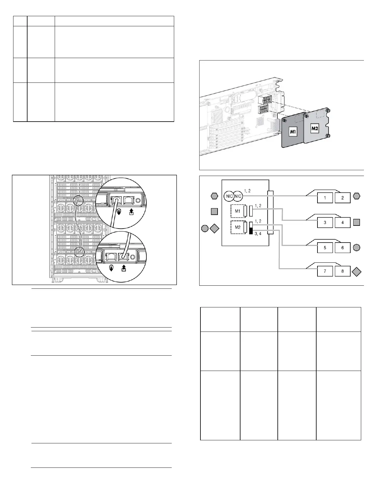
Mapping to interconnect ports
Several port types are referenced in the following tables.
• Examples of 1x ports are 1-Gb Ethernet (1 GbE) switch modules
and Fibre Channel interconnect modules.
• An example of a 2x port is a Serial Attached SCSI (SAS)
interconnect module. (Reserved for future use.)
• Examples of 4x ports are 10-Gb Ethernet (10 GbE) interconnect
modules.
NOTE: 1x and 2x port mezzanine cards interface with
single-wide interconnect modules. 4x port mezzanine
cards interface with double-wide interconnect modules.
The term "1x/2x" refers to the number of interconnect lanes per port
provided by the controller. The more lanes provided per port, the
higher the data transmission rate coming from that port.
Mapping half-height blades
The following table lists the available configurations for half-height
devices installed in device bay N (1–16).
Connection Port number
Connects to
interconnect
bay/port
Comments
Embedded
NIC
NIC 1
NIC 2
1/Port N
2/Port N
One or two
single-wide
Ethernet
interconnect
modules
Mezzanine slot
1—1x or 2x
cards
1x/2x port 1
1x/2x port 2
3/Port N
4/Port N
• One
single-wide
interconnect
module
• Four port
cards will
only connect
the first two
ports.

 Loading...


