11
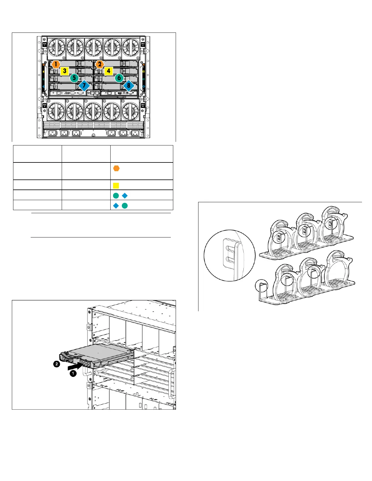
Installing interconnect modules
Server blade signal
Interconnect bay
number
Interconnect bay label
NICs 1, 2, 3, and
4 (embedded)
1, 2
Mezzanine 1 3, 4
Mezzanine 2 5, 6 and then 7, 8
Mezzanine 3 7, 8 and then 5, 6
NOTE: For information on the location of LEDs and ports
on individual interconnect modules, see the documentation
that ships with the interconnect module.
1. Install the interconnect modules based on the number ordered
and the number of fabrics in the configuration.
The enclosure ships with interconnect bay dividers installed. The
interconnect bay dividers must be removed before installing
double-wide interconnect modules. To remove an interconnect
bay divider, press the release tab, and pull the interconnect bay
divider out of the enclosure.
2. Install interconnect blanks in any unused interconnect bays.
3. Connect each installed interconnect module to the external
connections with the appropriate cable.
Powering up the enclosure
Single-phase power configuration
For a single phase power configuration:
1. Connect the AC power cables to the power connectors on the
rear of the enclosure corresponding to the power supply that was
populated on the front of the enclosure.
2. Be sure each power cable is securely attached to the power
connectors.
3. Connect the AC power cables to the AC power source or to an
installed power distribution unit (PDU).
4. Turn on the AC circuit breakers that power the power cables
installed in the enclosure.
5. Locate the power retention bracket that came with the enclosure.
6. Verify that the power cord retention tabs are on the correct side.
o On the left side: To install the power cord retention bracket
on the left side of the enclosure, ensure the power cord
retention tabs are located to the right of the snap clamps.
o On the right side: To install the power cord retention bracket
on the right side of the enclosure, ensure the power cord
retention tabs are located on the left side of the snap clamps.
7. Place the power cord retention bracket under the power cords,
and then align the power cords with the snap clamps.
8. Open the snap clamps, and then insert each power cord inside
each clamp.
9. Slide the power cord retention bracket until the bracket touches
the enclosure.

 Loading...


