EasyManuals Logo

HP Compaq Pro 6300 Series Microtower User Manual

HP Compaq Pro 6300 Series Microtower
233 pages
To Next Page IconTo Next Page
To Previous Page IconTo Previous Page
Page #91 background imageLoading...
Page #91 background image
Power Switch/LED Assembly
Description Spare part number
Power switch/LED assembly 646828-001
1. Prepare the computer for disassembly (Preparation for Disassembly on page 54).
2. Remove the access panel (
Computer Access Panel on page 55).
3. Remove the front bezel (
Front Bezel on page 56).
4. Remove the front fan (
Front Fan Assembly on page 79).
5. Disconnect the cable from the system board connector labeled PB/LED.
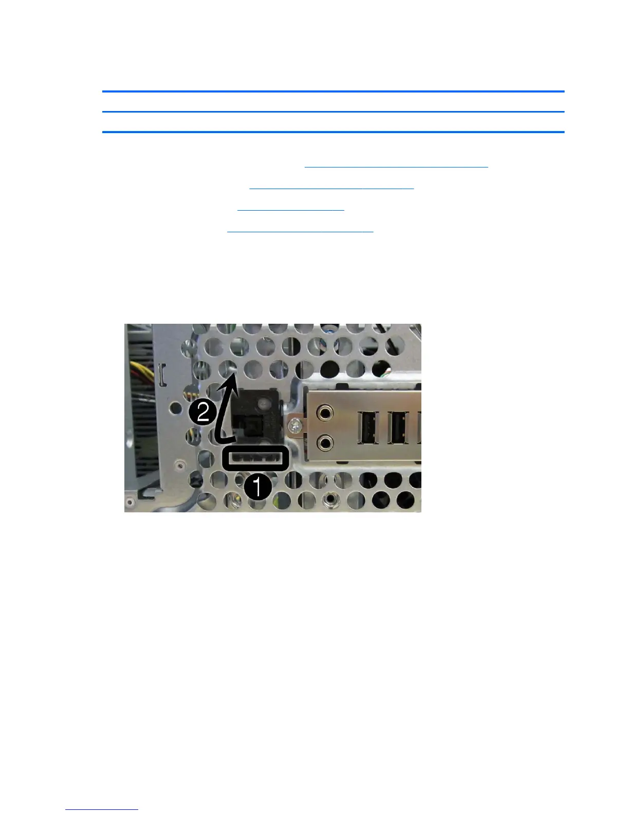
6. With the computer on its side, press on the tabs on the bottom of the assembly (1) to disengage
the assembly from the chassis, and then rotate the bottom of the assembly upward (2) to
remove it from the chassis.
Figure 6-30 Removing the power switch/LED
7. Pull the assembly away from the chassis while threading the cable through the hole in front of
the chassis.
82 Chapter 6 Removal and Replacement Procedures Microtower (MT) Chassis

Table of Contents

Questions and Answers:

Question and Answer IconNeed help?

Do you have a question about the HP Compaq Pro 6300 Series Microtower and is the answer not in the manual?

HP Compaq Pro 6300 Series Microtower Specifications

General IconGeneral
Form FactorMicrotower
ProcessorIntel Core i3/i5/i7
ChipsetIntel Q75 Express
MemoryUp to 32 GB DDR3
Storage256 GB Solid State Drive
GraphicsIntel HD Graphics or optional discrete graphics
Optical DriveDVD-ROM
Operating SystemWindows 7 Professional, Windows 8 Pro, FreeDOS
PortsUSB 2.0/3.0, VGA, DisplayPort
NetworkIntegrated Intel 82579LM Gigabit Network Connection
AudioHigh Definition Audio with Realtek ALC221 codec
Power Supply320W
Expansion Slots1 PCIe x1
WeightApprox. 16.5 lbs

Related product manuals