Removal and Replacement Procedures
Maintenance and Service Guide 5–27
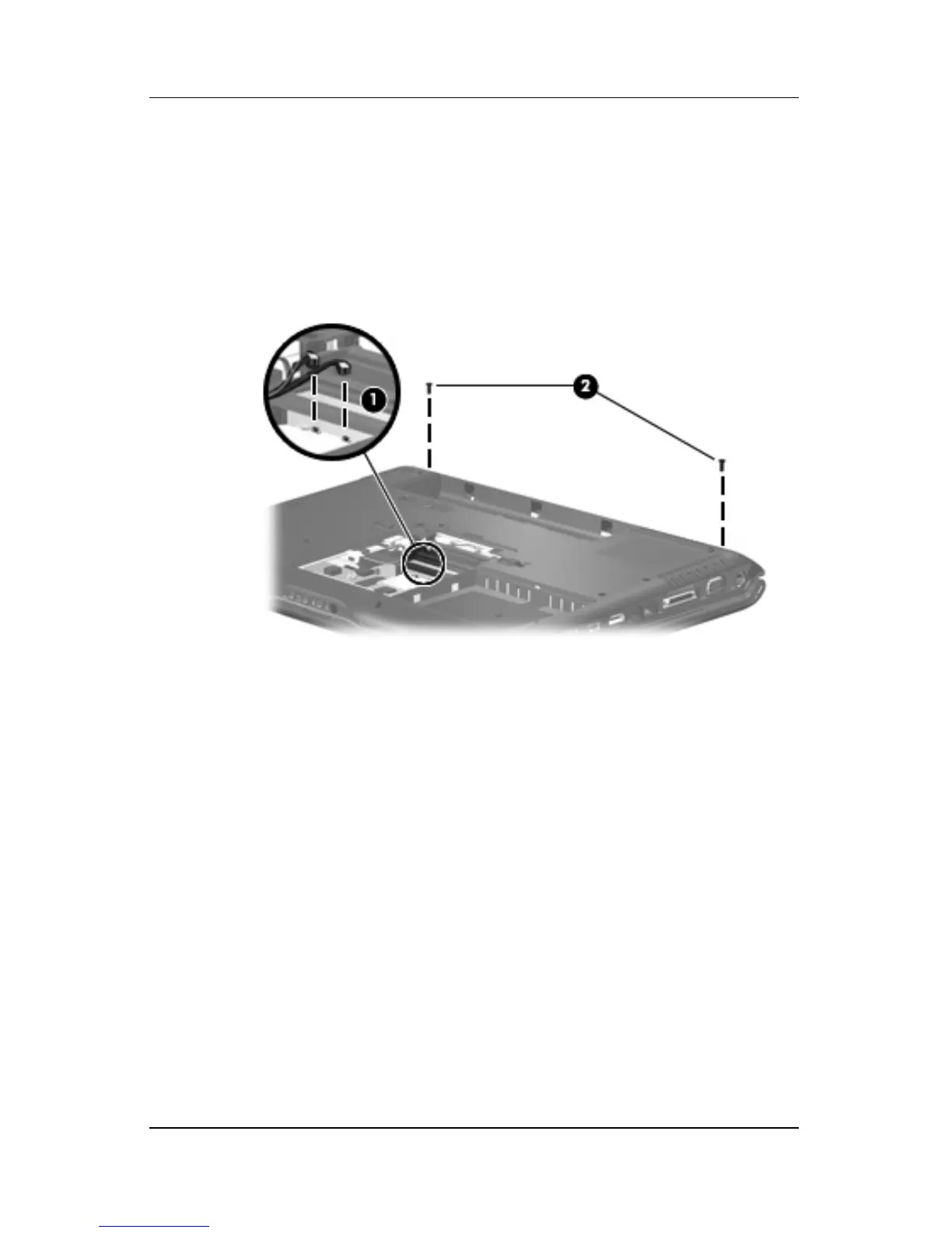
4. Make note of which wireless antenna cable is attached to
which antenna clip on the Mini Card module before
disconnecting the cables. Then disconnect the cables 1 from
the module.
5. Remove the two Phillips PM2.5×7.0 screws 2 that secure the
display assembly to the computer.
Removing the Display Assembly Screws
6. Turn the comuter display-side up with the front toward you.
7. Open the computer to an upright position.