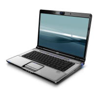
5–56 Maintenance and Service Guide
Removal and Replacement Procedures
5.21 Fan/Heat Sink Assembly
✎
When replacing the fan/heat sink assembly, be sure the power
button board is removed from the defective fan/heat sink
assembly and installed on the replacement fan/heat sink
assembly. Refer to Section 5.13, “Power Button Board,” for
power button board removal information.
1. Prepare the computer for disassembly (Section 5.3) and
remove the following components:
❏ Hard drive (Section 5.4)
❏ Optical drive (Section 5.9)
❏ Switch cover (Section 5.10)
❏ Keyboard (Section 5.11)
❏ Speaker assembly (Section 5.12)
❏ Display assembly (Section 5.14)
❏ Top cover (Section 5.15)
❏ Audio board (Section 5.16)
❏ USB/power connector board (Section 5.19)
❏ System board (Section 5.20)
2. Turn the system board upside down with the expansion port 3
and external monitor port toward you.
Fan/Heat Sink Assembly Spare Part Number Information
For use with full-featured computer models
For use with defeatured computer models
431449-001
431448-001