5–32 Maintenance and Service Guide
Removal and Replacement Procedures
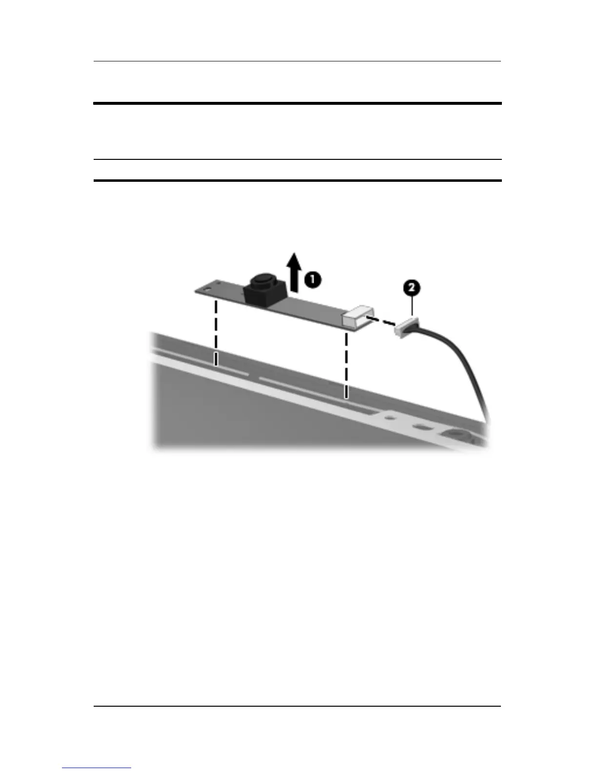
15. Remove the camera module 1 from the display enclosure.
16. Disconnect the camera cable 2 from the camera module.
Removing the Camera Module
Display Assembly Subcomponents
Spare Part Number Information
Camera module 431392-001