5–38 Maintenance and Service Guide
Removal and Replacement Procedures
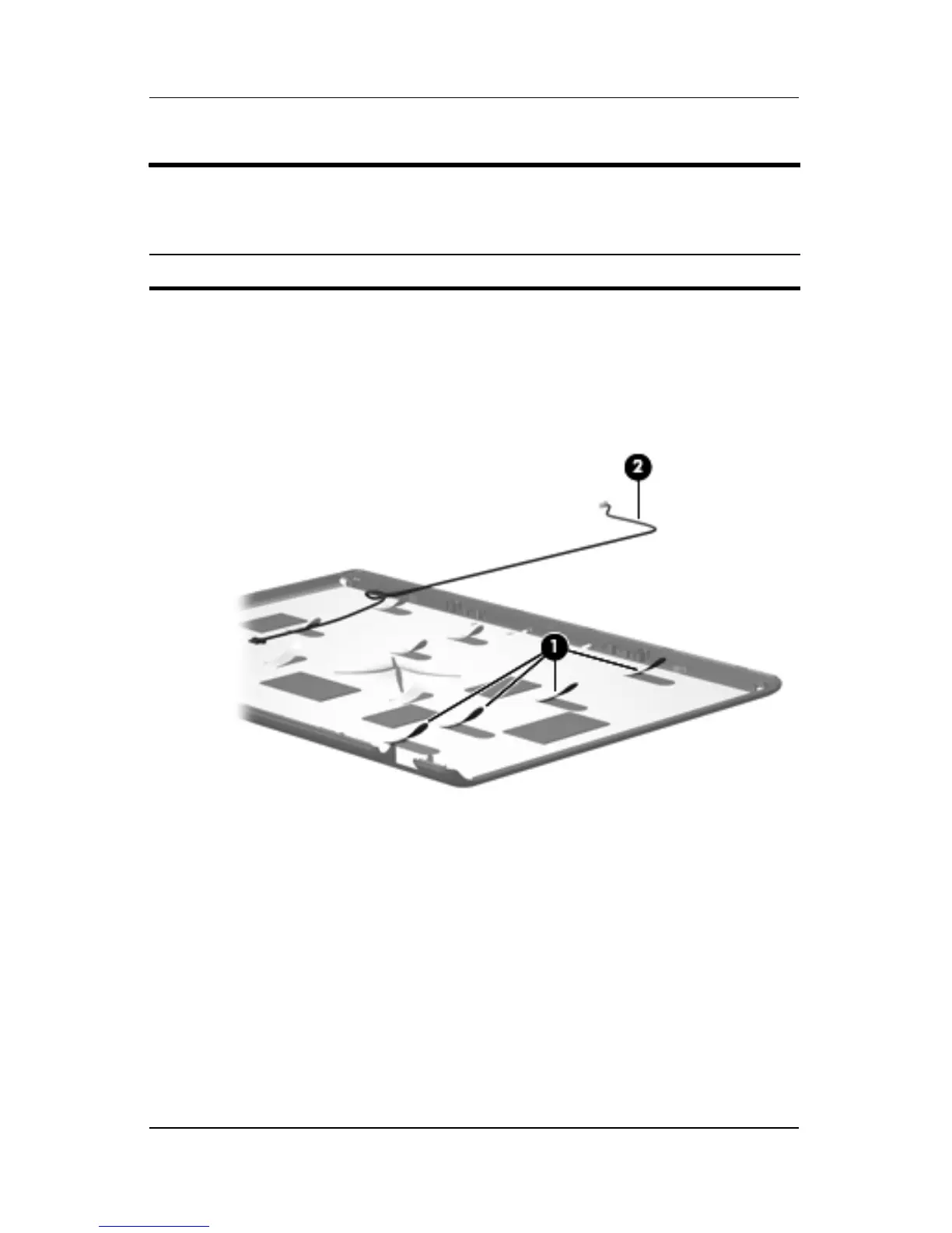
31. If it is necessary to replace the camera cable, release the
retention tabs 1 built into the display enclosure that secure
the camera cable to the display enclosure.
32. Remove the camera cable 2 from the display enclosure.
Removing the Camera Cable
Reverse the above procedure to reassemble and install the
display assembly
Display Assembly Subcomponents
Spare Part Number Information
Display Cable Kit (includes camera cable) 431394-001