5–40 Maintenance and Service Guide
Removal and Replacement Procedures
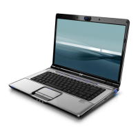
2. Turn the computer upside down with the front toward you.
3. Remove the nine Phillips PM2.5×7.0 screws that secure the
top cover to the computer.
Removing the Top Cover Screws, Part 1
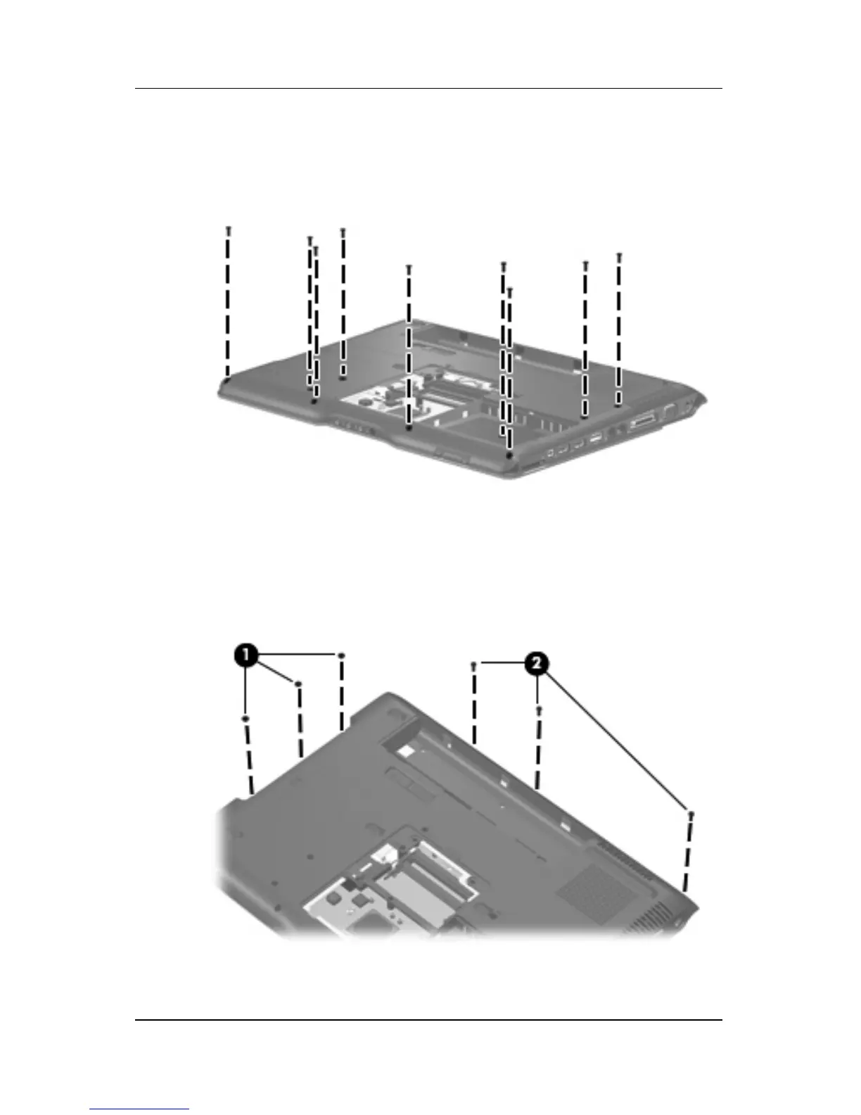
4. Remove the three Phillips PM2.5×2.0 screws 1 and the
three Phillips PM2.5×7.0 screws 2 that secure the top cover
support trim to the computer.
Removing the Top Cover Screws, Part 2