Removal and Replacement Procedures
Maintenance and Service Guide 5–51
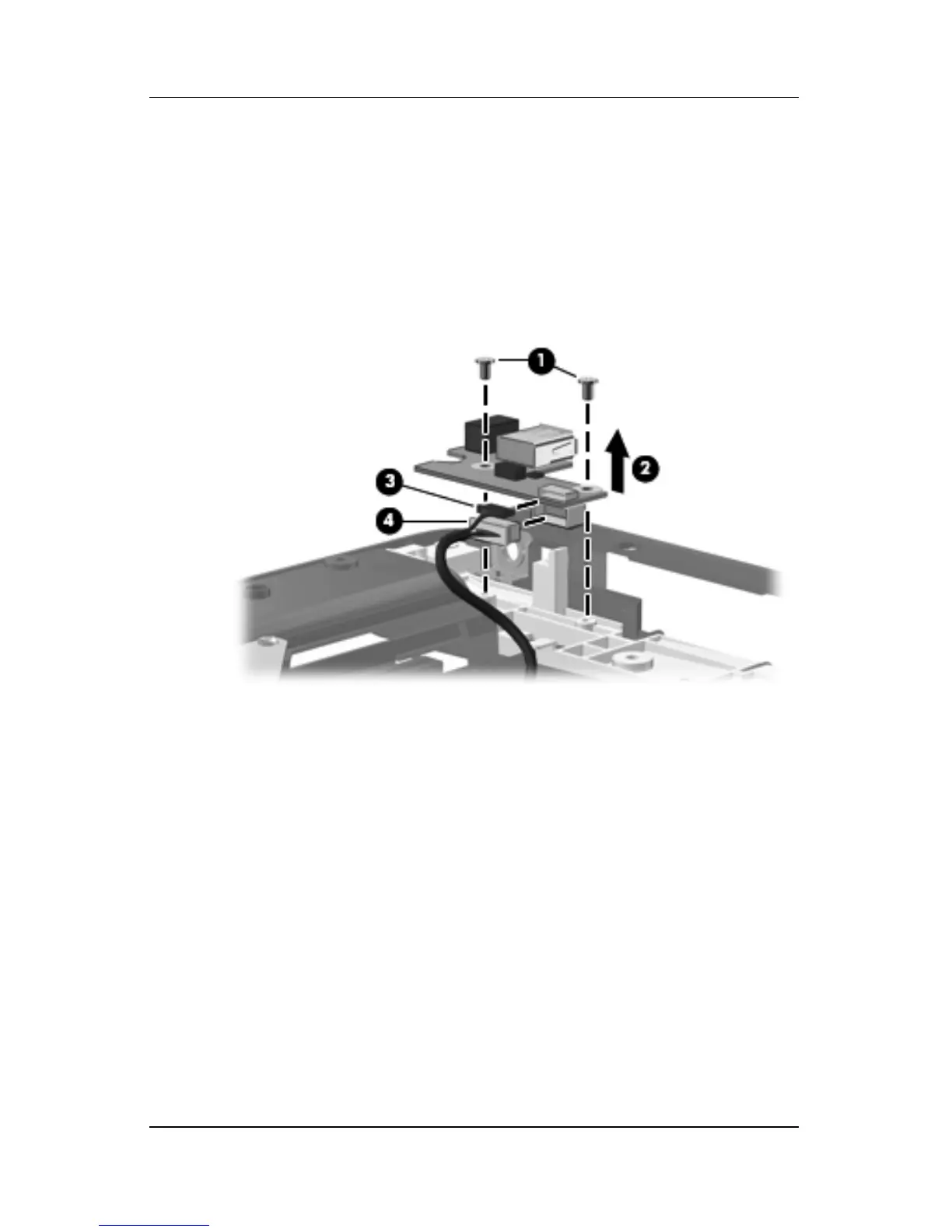
2. Remove the two Phillips PM2.5×5.0 screws 1 that secure the
USB/power connector board to the computer.
3. Release the USB/power connector board 2 as far as the
USB/power connector board cable will allow.
4. Disconnect the USB board cable 3 and the power connector
board cable 4 from the USB/power connector board.
Removing the USB/Power Connector Board
5. Remove the USB/power connector board.
Reverse the above procedure to install the USB/power
connector board.